|
Type
| Function blockAvailable as standard (non-safety-related) and safety-related type (*_S). For the safety-related type, the safety-related data types (SAFE*) are expected at the formal parameters.
Note
Both the standard and the safety-related type are only available in safety-related code (SNOLD), i.e. in a safety application executed by a Safety PLC. |
|
|
Description
| Generates a pulse signal with configurable pulse/pause ratio. Pulse duration and pause time (pulse ratio) can be set using the function block inputs PTH and PTL.
The pulse signal output can be used to control other (safety-related or standard) functions/function blocks.
Unintended machine operation
Verify that the connection of the pulse signal generated by PULSE_GEN/PULSE_GEN_S cannot lead to undesirable behavior of the safety-related application.1 |
| 1 | This could occur, for example, if the Q output of PULSE_GEN is connected to the Reset input of a safety-related function block, thereby causing potentially hazardous cyclic resetting. |
|
|
Notes
| Function blocks have to be instantiated. The instance name of the function block has to be declared in the 'Variables' table of the POU where the FB is going to be used. The instance name must be unique within the POU. |
|
Parameters
| Inputs
 IN IN
| Data type: | (SAFE)BOOL |
| Description: | State-controlled input for activating the FB. Connect this input to a TRUE constant or a Boolean/Safeboolean input signal:
-
TRUEThe FB is activated, the time inputs PTH and PTL are evaluated, and the pulse signal is output accordingly at Q.
Note
The Q output is set to TRUE immediately when the FB is activated (IN = TRUE). Each pulse train always starts with a rising edge at the Q output. States are not considered relevant when the FB is deactivated. |
-
FALSE
The FB is not activated. The output is switched to FALSE.
Note
If the FB is connected to the safety-related function block SF_TestableSafetySensor (TSS)
in such a way that a positive edge of the Q output signal at the StartTest input of the TSS function block will trigger the sensor test, the IN input of the pulse generator FB must always be connected to the TRUE constant as shown in the application example below. You must always validate the entire safety function. |
|
PTH / PTL
| Data type: | (SAFE)TIME |
| Description: | Inputs for specifying the pulse ratio of the output signal:
- PTH - duration of the TRUE state at the Q output (pulse duration)
- PTL - duration of the FALSE state at the Q output (pause time)
Note
Pulse duration and pause time can be set to different values.
Pulse duration (PTH) > pause time (PTL) and vice versa are permitted. |
Note
Only time values which are higher than the cycle time of the Safety PLC are compatible.
The FB does not recognize incorrectly set time values. As such, no error message will be output if the time slot is set too large or too small. |
Unintended machine operation
Verify that the time values applied to PTH and PTL correspond to the time values from the risk analysis you carried out for your application. |
|
Output
Q
| Data type: | (SAFE)BOOL |
| Description: | Outputs the generated pulse signal with the pulse/pause ratio according to the time values set at the inputs PTH and PTL (for example with ratio 2:3 as shown in the timing diagram below).
Note
The Q output is set to TRUE immediately when the function block is activated (IN=TRUE). Each pulse train always starts with a rising edge at the Q output. States are not considered relevant when the FB is deactivated. |
|
ETH/ETL
| Data type: | (SAFE)TIME/LTIME
|
| Description: | ETH (Elapsed Time High) shows the elapsed pulse time while Q = TRUE. ETL (Elapsed Time Low) shows the elapsed pause time while Q = FALSE. |
|
|
Fault Avoidance
|
Unintended machine operation
Validate the entire safety function to ensure correct time values set at the PTL and PTH inputs. |
Possible error sources (signals):
Impermissible signals at the IN input
If no further measures for fault avoidance are taken, signal levels at the IN input which change or toggle sporadically will cause the pulse generator to restart on each and every positive edge. A TRUE pulse at the Q output will be set to FALSE immediately on a negative edge.
Undesirable connection of the IN input
If no further measures for fault avoidance are taken, the undesirable connection of the IN input to a signal not designated for this purpose will cause the signal connected in error to control pulse generation. As a result, the pulse generator will be restarted on every positive edge. A TRUE pulse at the Q output will be set to FALSE immediately on a negative edge.
Impermissible static TRUE signal at the IN input (operating current principle)
If no further measures for fault avoidance are taken, a static TRUE signal at the IN input will cause the pulse generator to run continuously and it will not be possible to stop it.
Impermissible static FALSE signal at the IN input (closed-circuit current principle)
If no further measures for fault avoidance are taken, a static FALSE signal at the IN input will cause the pulse generator to be idle continuously and it will not be possible to start it.
Connection with
safety-related function block SF_TestableSafetySensor: Impermissible FALSE signal or no connection at the IN input
If the pulse generator FB is connected to the safety-related function block SF_TestableSafetySensor (TSS) in such a way that a positive edge of its Q output signal at the StartTest input of the TSS function block will trigger the sensor test, the IN input of the pulse generator FB must always be connected to the TRUE constant as shown in the application example below. You must always validate the entire safety function.
Possible causes:
- Programming errors in the application program (user errors)
- Cross-circuit, short-circuit, and cable break (user errors, wiring errors)
Possible preventive measures (depending on the safety function):
- Use of
safety-related device signals
- Use of options for cross-circuit detection
- Verification of the safety-related logic in the code editor and subsequent validation of the entire
safety-related application code
|
|
Timing Diagram
| Timing Sequence for pulse ratio 2:3 (PTH=2.0 s and PTL=3.0 s, for example):
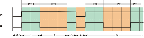
| 0 | The FB is not yet activated (IN = FALSE). Q is FALSE. |
| 1 | With IN = TRUE, Q is set to TRUE immediately; the FB retains this state for the time set at the PTH input. |
| 2 | Once the pulse duration PTH has expired, the output is set to FALSE; the FB retains this state for the time set at the PTL input. |
| 3 | After expiration of PTL, Q is set to TRUE. |
| 4 | While Q = TRUE, the FB is deactivated during PTH (IN changes to FALSE). Q immediately switches to FALSE. |
| 5 | The FB is activated (IN switches to TRUE). The pulse train starts again, Q switches to TRUE immediately.
The output will toggle between TRUE and FALSE in accordance with the time set (PTH and PTL) for as long as IN = TRUE. |
|
|
Application Example
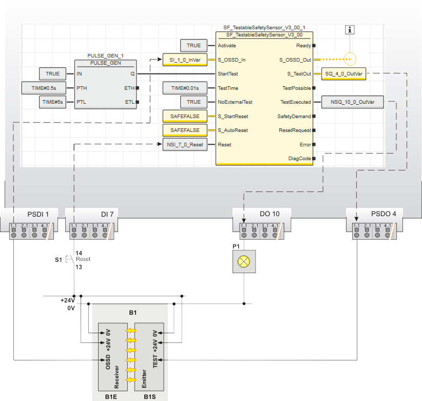
| Application example for periodic start of a sensor
In this example, the pulse generator starts a sensor test periodically. For this purpose, the Q output of the pulse generator is connected to the StartTest input of the safety-related function block SF_TestableSafetySensor. A positive edge at this input starts the sensor test of the connected safety sensor.
Fault avoidance when using the pulse generator FB with the safety-related function block SF_TestableSafetySensor:
With the correct connection shown in the example graphic below, a pulse at the Q output of PULSE_GEN does not guarantee that the sensor test will actually be carried out. This is because in order for the sensor test to be carried out, the SF_TestableSafetySensor function block must permit it. In other words, the TestPossible TSS output must be set to TRUE when the pulse generated by PULSE_GEN is present at the StartTest TSS input. You must take this into account in the context of your risk analysis.
Unintended machine operation
Validate the entire safety function in terms of the correct interaction of the function blocks PULSE_GEN and SF_TestableSafetySensor, if they are used in the way described in this application example. |
Note
In this application with the safety-related function block SF_TestableSafetySensor, the IN input of the PULSE_GEN FB mustalways be connected to the TRUE constant as shown in the graphic below.
The frequency of the sensor test (test interval) is thus set using PTL input of the pulse generator. The pulse duration (PTH input) is of no relevance to this application. |
Further Info
You will find more detailed information about the safety-related function block SF_TestableSafetySensor
and how it is connected underneath the graphic, as well as in the online help for the SF_TestableSafetySensor function block. |
| S1 | Reset |
B1
B1S
B1E | ESPE - optoelectronic sensor: Single-channel light grid with test input
Optoelectronic emitter
Optoelectronic receiver |
| P1 | Signal lamp |
 | See note below
|
The connected sensor is a single-channel connected light grid. The SF_TestableSafetySensor function block is connected/configured as follows:
- Both function blocks are permanently activated by the TRUE constant at the IN input (PULSE_GEN) and the Activate input (TSS).
- The status signal of the sensor is connected to the input terminal 1.1 of the
safety-related input device PSDI 1. This terminal is assigned to the global input variable SI_1_0 which is fed to the function block input S_OSSD_In for evaluation.
- The function block output S_TestOut outputs the start signal for the sensor test to the sensor. The sensor's test input is connected to output 1.1 of the
safety-related output device PSDO 4 (assigned to the global output variable SQ_4_0).
- The function block output TestExecuted signals the successfully executed sensor test. It is connected to a standard global output variable which is in turn assigned to terminal 1.1 of the standard output device DO 10. A signal lamp is connected to this terminal.
- Input S_StartReset = SAFEFALSE specifies a start-up inhibit after the controller has been started up or the function block has been activated. In addition, S_AutoRestart = SAFEFALSE specifies a restart inhibit for the function block after the TRUE signal returns at the S_OSSD_In input (in other words, the safety sensor's light beam is no longer interrupted). These two start-up inhibits are only removed when there is a positive signal edge at the Reset input. To this end, the S1 reset button is connected to terminal 1.1 of the standard input device DI 7. This standard device terminal is assigned to the global standard input variable NSI_7_0.
Note
The S_OSSD_Out enable output of the SF_TestableSafetySensor function block is connected to a global output variable (i.e., to an output terminal of the application), either directly or via other
safety-related functions/function blocks. |
|