TestTime input
Specification of the permissible response time for the signal changes of the individual sensor test phases.
Data type: TIME
Initial value: #10ms
Permissible maximum value: #150ms
| Note
The diagram only shows the inputs and outputs relevant for the description, and only a successful test is displayed. |
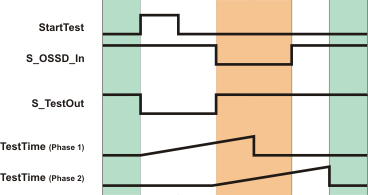
Sensor test phase 1: A rising edge at the StartTest input causes the S_TestOut output to switch to SAFEFALSE and the monitoring time set at TestTime (phase 1) to begin. The sensor must switch the S_OSSD_In input to SAFEFALSE within the period specified at TestTime.
Sensor test phase 2: Once there is a SAFEFALSE at the S_OSSD_In input, the S_TestOut output is switched to SAFETRUE and a second monitoring time measurement (phase 2) begins with the time set at TestTime. The sensor must switch the S_OSSD_In to SAFETRUE within this period.
If one of the two time monitoring periods is exceeded, the function block switches the S_OSSD_Out output to SAFEFALSE and outputs an error (Error = TRUE) at the Error output.
Connection: Connect this input to a time literal, i.e., to a constant of the data type TIME.
| Note
An automatic test cycle extends the total response time for the safety-related function. This means the value for TestTime depends on the safety-related application involved and must be established as part of a risk analysis. Do not enter any other value than this. |
|
WARNING
|
Non-conformance to safety function requirements
|