- Home
- Function/Function Block Reference
- Safety-Related PLCopen Function Blocks
- SF_EDM (External Device Monitoring)
SF_EDM (External Device Monitoring)
Help version 1.1 / Issue date: 2018.03
The following description is valid for the function block SF_EDM_V2_0z, Version 2.0z (where z = 0 to 9).
| Short Description | The safety-related SF_EDM (External Device Monitoring) function block monitors the defined initial state and the switching behavior of contactors connected to the Safety PLC.S_StartReset can be used to specify a start-up inhibit.
|
||||||||||||||||||||||||||||||||
| Block Icon | |||||||||||||||||||||||||||||||||
| Inputs |  Activate Activate
Refer to the topic "Activate" for details. S_OutControl
Refer to the topic "S_OutControl" for details. S_EDM1 and S_EDM2
Refer to the topic "S_EDM1 and S_EDM2" for details. MonitoringTime
Refer to the topic "MonitoringTime" for details. S_StartReset
Refer to the topic "S_StartReset" for details. Reset
Resetting the function block by means of a positive signal edge at the Reset input can cause the S_EDM_Out output to switch to SAFETRUE immediately (depending on the status of the other inputs).
Refer to the topic "Reset" for details. |
||||||||||||||||||||||||||||||||
| Outputs | Ready
Refer to the topic "Ready" for details. S_EDM_Out
Refer to the topic "S_EDM_Out" for details. SafetyDemand
Refer to the topic "SafetyDemand" for details. ResetRequest
Refer to the topic "ResetRequest" for details. Error
Refer to the topic "Error" for details. DiagCode
Refer to the topic "DiagCode" for details. |
||||||||||||||||||||||||||||||||
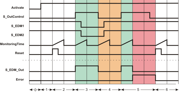
| Detailed information | Signal sequence diagram
This diagram is based on a typical interconnection with a start-up inhibit after the function block has been activated or the Safety PLC has started up (S_StartReset = SAFEFALSE).
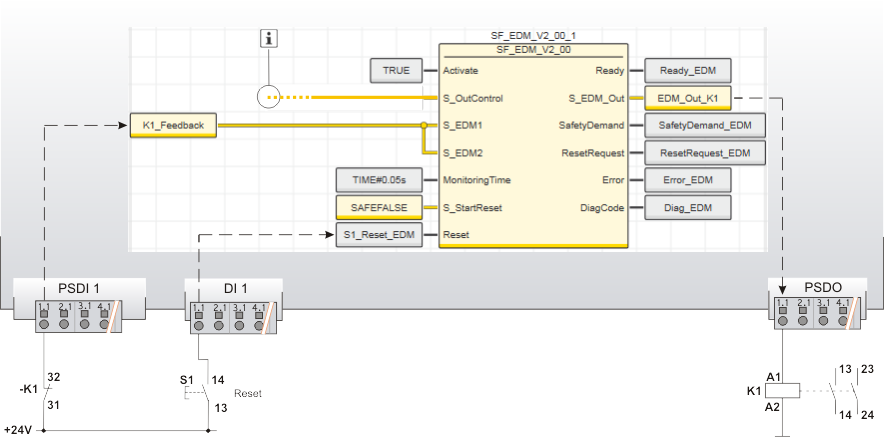
Application example
In this example, the safety-related SF_EDM function block monitors the switching behavior of a contactor K1 connected to output terminal 1.1 of the safety-related output device PSDO. Via input terminal 1.1 of the safety-related input device PSDI 1, an N/C contact provides single-channel feedback signal from the contactor to the S_EDM1 and S_EDM2 inputs (single-channel application up to Cat. 2). The resulting signal of the input terminal is assigned to the global I/O variable K1_Feedback. The reset button S1 is connected to the input terminal 1.1 of the standard input device DI 1. The signal at input terminal 1.1 assigned to the global I/O variable S1_Reset_EDM is used to remove the start-up inhibit and reset the error states after the cause of the error has been removed.
Function block instantiation
The IEC 61131-3 standard defines function block instantiation. Instantiation means, a function block is defined once and can be used (instantiated) several times. This applies to all FBs (user-defined POUs as well as library FBs, such as IEC standard FBs, firmware FBs, user library FBs).
Why instantiation? The following applies:
The user-defined function block 'TLC' ("Two Level Controller") is added to the 'Functions & Function Blocks' category (COMPONENTS area). It shall be called twice in the program POU 'Container' to control the filling level and the temperature of a boiler. For both FB instances, an instance name declaration is added to the 'Variables' table of the calling program POU 'Container': TLCTemperature and TLCLevel. Thus the 'TLC' function block can be called twice in the code worksheet of the calling POU by means of these instance names.
|