The diagram below shows the signal sequence of a typical application, based on the following assumptions:
S_StartReset = SAFEFALSE: Start-up inhibit after the function block has been activated and the Safety PLC has started up.
S_AutoReset = SAFEFALSE: Restart inhibit after the guard locking on the closed safety equipment has been locked (i.e., once the SAFETRUE signal has returned at the S_GuardLock input).
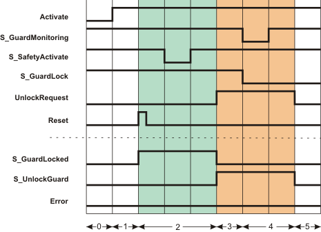
| 0 | The function block is not yet activated (Activate = FALSE). As a result, all outputs are FALSE or SAFEFALSE. |
| 1 | Function block activated by Activate = TRUE. Even though the safety equipment is closed (S_GuardMonitoring = SAFETRUE) and locked (S_GuardLock = SAFETRUE) and the zone of operation signals the defined safe state (S_SafetyActive = SAFETRUE), the S_GuardLocked output = SAFEFALSE, as a start-up inhibit (S_StartReset = SAFEFALSE) is specified. |
| 2 | A positive edge at the Reset input removes the start-up inhibit and the S_GuardLocked output switches to SAFETRUE.The S_GuardLocked output remains SAFETRUE, although the S_SafetyActive input is SAFEFALSE for some time (zone of operation is temporarily no longer in the defined safe state). |
| 3 | The request to unlock the guard locking triggered by UnlockRequest = TRUE and the confirmation that the zone of operation is in the defined safe state again (S_SafetyActive = SAFETRUE) cause the S_GuardLocked output to switch to SAFEFALSE and the S_UnlockGuard output to SAFETRUE.The S_UnlockGuard output remains SAFETRUE for as long as the unlock request is present at the UnlockRequest input. |
| 4 | The safety equipment is opened (S_GuardMonitoring and S_GuardLock both become SAFEFALSE) and closed again (S_GuardMonitoring becomes SAFETRUE again), but not locked after closing (S_GuardLock remains SAFEFALSE). Therefore, the S_GuardLocked output remains SAFEFALSE. |
| 5 | The S_UnlockGuard output switches to SAFEFALSE, as input UnlockRequest is now also FALSE. The safety equipment is not yet locked (S_GuardLock is still SAFEFALSE). |
This example describes the connection of a single-channel guard with lockable guard locking to the safety-related SF_GuardLocking 2 function block. A start-up inhibit and a restart inhibit are specified.
In this example, the arrangement of the switch meets the requirements of DIN EN ISO 14119, Appendix F.
The door switch and the contact for confirmation of locking have a single-channel connection to the inputs of the Safety PLC. The coil for opening the interlock also has a single-channel connection to an output of the Safety PLC.
The sensors/actuators are connected to the Safety PLC and function block as follows:
- The mechanically actuated position switch B1 (door switch) is connected to input terminal 1.1 of the safety-related input device PSDI 1. Its signal is assigned to the global I/O variable B1_GMON_In and connected to the S_GuardMonitoring input of the function block.
- The guard locking feedback signal is connected to input terminal 3.1 of the safety-related PSDI 1 input device. Its signal is assigned to the global I/O variable K1_GLOC_In and connected to the S_GuardLock input of the function block.
- Button S2 is connected to input terminal 1.1 of the standard input device DI 1; the TRUE signal of this button triggers a request to unlock the door. The assigned global I/O variable S2_UREQ_In is connected to the UnlockRequest input of the function block.
- Reset button S3 is connected to the input terminal 3.1 of the standard input device DI 1. Its signal is assigned to the global I/O variable S3_Reset_GL and connected to the Reset input of the function block. The signal of this button is used to reset error states of the function block and to remove the start-up inhibit/restart inhibit (see below).
- The S_UnlockGuard output signal of the function block controls the coil for opening the interlock via the connected global I/O variable K1_ULOCK_Out. This coil K1 is connected to the output terminal 1.1 of the safety-related output device PSDO, which is in turn assigned to K1_ULOCK_Out.
S_StartReset and S_AutoReset are both switched to SAFEFALSE, in other words:
- S_StartReset = SAFEFALSE: Start-up inhibit after the Safety PLC has been started up and the function block has been activated.
- S_AutoReset = SAFEFALSE: Restart inhibit after the SAFETRUE signal has returned at the S_GuardLock input.
Note
The "Machine stopped"' signal is connected to input S_SafetyActive of the SF_GuardLocking 2 function block; this signal originates from a standstill monitor, for example.
The enable output S_GuardLocked of the SF_GuardLocking 2 function block is directly connected to a global I/O variable or to an output terminal of the application via further safety-related functions/function blocks.
Connect the S_GuardLocked enable output of the SF_GuardLocking 2 function block to the S_OutControl input of the SF_EDM function block, for example, thus implementing a two-channel output connection. |
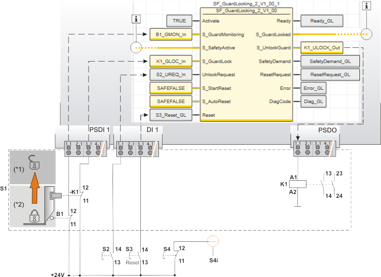
| S1 | Safety-related switch with guard locking, contains
- Door switch (B1), single-channel
- Lock monitoring of the guard locking (contact -K1) and
- Coil (K1) for opening the interlock |
| (*1) | Guard locking of S1: open |
| (*2) | Guard locking of S1: closed |
| S2 | Request to unlock the door |
| S3 | Reset button for resetting errors and removing an active start-up inhibit/restart inhibit |
| S4 | Button for stopping the machine. |
| S4i | Signal for stopping the machine. |
 | See note above the illustration. |
The IEC 61131-3 standard defines function block instantiation. Instantiation means, a function block is defined once and can be used (instantiated) several times. This applies to all FBs (user-defined POUs as well as library FBs, such as IEC standard FBs, firmware FBs, user library FBs).
Why instantiation?
A function block has an internal memory where it stores its own processing data (local variables). As a consequence, the output values calculated by the FB depend on the internally stored values. The same input values applied to an FB instance do not necessarily deliver the same results in another FB instance.
Therefore, it is necessary to store the internal data of the FB to a separated memory area each time the function block is processed, i.e., for each FB instance. To uniquely identify each FB instance and to clearly separate its memory area, instance names are used.
The instance name of the function block has to be declared in the 'Variables' table of the POU where the FB is going to be used.
The following applies:
- Function blocks can be instantiated in other function blocks or in program POUs. Calling FBs in function POUs is not possible.
- Functions are called without instantiation because they do not have an internal memory.
Safety-related and standard (non-safety-related) code is strictly distinguished in PLCnext Engineer. If a Safety PLC is included in your project, the following applies:
- Safety-related FBs can only be instantiated in safety-related POUs but not in standard (non-safety-related) POUs.
- User-defined standard FBs can only be instantiated in standard POUs. They cannot be called in safety-related POUs.
- Particular standard firmware FBs can be instantiated in both safety-related and standard POUs.
Note
When inserting a standard FB into a safety-related SNOLD network, the rules for implicit type conversion (safety-related to standard) apply. |
 Example for the instantiation of a user-defined function block
The user-defined function block 'TLC' ("Two Level Controller") is added to the 'Functions & Function Blocks' category (COMPONENTS area). It shall be called twice in the program POU 'Container' to control the filling level and the temperature of a boiler.
For both FB instances, an instance name declaration is added to the 'Variables' table of the calling program POU 'Container': TLCTemperature and TLCLevel. Thus the 'TLC' function block can be called twice in the code worksheet of the calling POU by means of these instance names.
Both FB instances have been inserted into the 'Container' code worksheet, each instance with different variables connected to its input and output formal parameters ('Level...' and 'Temperature...').
