This diagram refers to a typical signal sequence, in which the request of a safety-related function is supported.
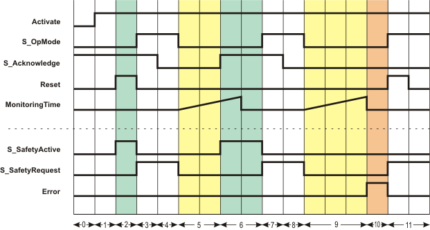
The incoming request of a safety-related function by a SAFEFALSE signal at input S_OpMode controls the S_SafetyRequest output directly and without additional dependencies for a request for the safety-related function at the connected safety-related periphery. In the example shown, two requests for the safety-related function occur. Consequently, the time monitoring between the request of a safety-related function and the confirmation message from the safety-related periphery is started twice.
During the first time monitoring, feedback occurs through S_Acknowledge = SAFETRUE within the time parameterized at MonitoringTime, and the S_SafetyActive enable output switches to SAFETRUE (phases 5 and 6 in the diagram).
In the second case, the parameterized time value is exceeded. The function block then detects an error (Error = TRUE) and S_SafetyActive = SAFEFALSE signals that the safety-related periphery is not executing the requested safety-related function (phases 9 to 11 in the diagram).
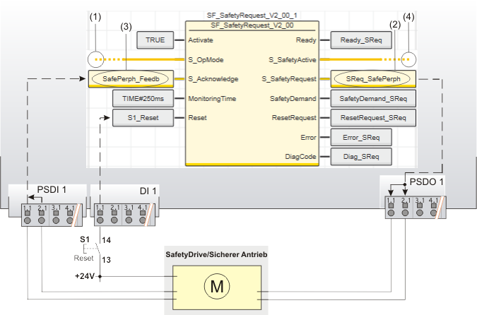
This example shows the exemplary use of the safety-related SF_SafetyRequest function block in case of request and feedback of the safety-related function "safely limited speed" (SLS) of a safety-related drive.
The function block is perpetually activated by the TRUE constant at the Activate input. Reset button S1 is connected to the input 1.1 of the standard input device DI 1.
The relevant inputs and outputs are connected as follows:
- The S_OpMode input of the SF_SafetyRequest function block is directly connected to the S_Mode0Sel enable signal of the upstream SF_ModeSelector function block. The request for the safety-related function (of the evaluated mode selector switch) is consequently the selection of the operating mode 0. In our example this is the commissioning or maintenance mode in which the drive is operated with safely limited speed. (See digit (1) in the graphic below.)
- The S_SafetyRequest output is connected to the global I/O variable SReq_SafePerph, which in turn is assigned to the output 1.1 of the safety-related output device PSDO 1 (see (2) in the graphic below). The safety-related drive module is connected to the output terminals 1.1 and 2.1 using two channels here.
- The feedback signal for confirming the selected operating mode of the safety-related drive is connected as two-channel signal to the inputs 1.1 and 2.1 of the safety-related input device PSDI 1. The signal evaluated for equivalence by the safety-related input device is assigned to the global I/O variable SafePerph_Feedb and connected to the S_Acknowledge input of the SF_SafetyRequest function block for evaluation ((3) in the graphic).
- The S_SafetyActive enable output is connected to the S_SafetyActive input of the SF_EnableSwitch function block (see (4)). If the requested safely limited speed is confirmed by the safety-related drive at the S_Acknowledge input within the monitoring time specified at MonitoringTime, the S_SafetyActive enable output switches to SAFETRUE and thus signals the defined safe mode to the subsequent SF_EnableSwitch function block.
The IEC 61131-3 standard defines function block instantiation. Instantiation means, a function block is defined once and can be used (instantiated) several times. This applies to all FBs (user-defined POUs as well as library FBs, such as IEC standard FBs, firmware FBs, user library FBs).
Why instantiation?
A function block has an internal memory where it stores its own processing data (local variables). As a consequence, the output values calculated by the FB depend on the internally stored values. The same input values applied to an FB instance do not necessarily deliver the same results in another FB instance.
Therefore, it is necessary to store the internal data of the FB to a separated memory area each time the function block is processed, i.e., for each FB instance. To uniquely identify each FB instance and to clearly separate its memory area, instance names are used.
The instance name of the function block has to be declared in the 'Variables' table of the POU where the FB is going to be used.
The following applies:
- Function blocks can be instantiated in other function blocks or in program POUs. Calling FBs in function POUs is not possible.
- Functions are called without instantiation because they do not have an internal memory.
Safety-related and standard (non-safety-related) code is strictly distinguished in PLCnext Engineer. If a Safety PLC is included in your project, the following applies:
- Safety-related FBs can only be instantiated in safety-related POUs but not in standard (non-safety-related) POUs.
- User-defined standard FBs can only be instantiated in standard POUs. They cannot be called in safety-related POUs.
- Particular standard firmware FBs can be instantiated in both safety-related and standard POUs.
Note
When inserting a standard FB into a safety-related SNOLD network, the rules for implicit type conversion (safety-related to standard) apply. |
 Example for the instantiation of a user-defined function block
The user-defined function block 'TLC' ("Two Level Controller") is added to the 'Functions & Function Blocks' category (COMPONENTS area). It shall be called twice in the program POU 'Container' to control the filling level and the temperature of a boiler.
For both FB instances, an instance name declaration is added to the 'Variables' table of the calling program POU 'Container': TLCTemperature and TLCLevel. Thus the 'TLC' function block can be called twice in the code worksheet of the calling POU by means of these instance names.
Both FB instances have been inserted into the 'Container' code worksheet, each instance with different variables connected to its input and output formal parameters ('Level...' and 'Temperature...').