Safety PLC Commissioning: From Compiling to Debugging
|
WARNING
|
Unintended machine operation
|
| Note
Both the Safety PLC and the standard (non-safety-related) controller have their own, separate Cockpit and both can be connected and commissioned independently of each other. It is, for example, possible to write the standard application to the standard controller and start its execution while simulating the safety-related application. Safety download combined with standard download: However, it is possible to write and start the safety application together with the standard application. For that purpose, the commands 'Write and Start Project (incl. Safety)' (with and without project sources) are available in the Cockpit and the PLANT context menu of the standard controller. Instead of explicitly writing and starting only the safety application, you can use these commands to handle standard and safety application with one common command. Refer to the help topic "Controller Commissioning: From Compiling to Debugging". |
|
WARNING
|
Unintended machine operation
|
- Verify the following:
- The Safety PLC and all configured safety-related devices are available in the network.
- The application structure modeled in the PLANT represents the physical network.
- The IP address settings in the 'Settings' editor of each device involved are correct (controller node and PROFINET device nodes). If required, adjust the IP settings as described in the topic "Device Configuration/Parameterization".
Note
Usually, the Safety PLC has no own IP address. Instead, it has the same address as the controller which is to be set at the controller node. - No errors are pending in the Error List (MESSAGES window).
- The assignments (I/O mapping and exchange variables) in the Data List of the Safety PLC are correct and have been validated.
- If the Safety PLC or safety-related devices have been replaced since the last startup of the Safety PLC, you must verify that the Global Variables checksum (displayed in the 'Safety Information' editor) is identically before and after the safety device replacement. If the checksum differs, this indicates that the I/O mapping has been modified due to the device replacement. You must observe the hazard message and information given in the topic "Replacing Devices", section "Safety requirements when replacing the Safety PLC...".
- Make sure that the Safety PLC (not the Safety PLC simulation) is set as target system.
- Double-click the Safety PLC node in the PLANT to open its properties in the editors area.
- In the editors area, open the Safety Cockpit editor.
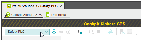
- In the Safety Cockpit editor, select 'Safety PLC' from the drop-down list.
- Creating the safety-related project image (building the project), sending it to the Safety PLC and starting the program execution is done with only one command.The safety-related project image contains the safety-related application logic as machine-readable code and all relevant configuration/parameterization data of the project. The safety-related project image can be executed by the Safety PLC.
Proceed as follows:Note
When writing the safety-related project image to the Safety PLC and starting the safety-related application, observe the safety warning message noted at the beginning of this topic.Refer to the topic "Controlling the safety-related application / Toolbar icons in the Safety Cockpit" for detailed information on the 'Write and Start' command.- In the PLANT, right-click the Safety PLC node and select 'Write and Start Project' from the context menu.
Example: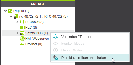
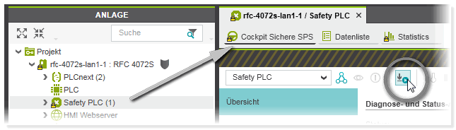
- Alternatively, click the following icon on the Safety Cockpit toolbar:
- The command is also available in the context menu of the Safety PLC in the ONLINE STATE window (which is located in the Cross Function Area at the bottom of the screen):

Note
'Write and Start' aborted due to compiler errors?
The project build process is aborted in case of any detected errors. After correcting the errors, you can use the commands 'Build' or 'Rebuild' to prove the error-free project before calling the 'Write and Start' command again. - In the PLANT, right-click the Safety PLC node and select 'Write and Start Project' from the context menu.
-
Not yet logged on to the standard controller? If the controller involved (which contains the Safety PLC) implements a secure device concept, and if you are not yet logged on to the controller (black shield symbol beside the controller icon in the PLANT), the logon dialog appears. Enter a user name of the desired and suitable role as well as the relating password and press <Enter> to log on. (Make sure that the user role you are entering allows writing and starting the safety-related project.)
If an authentication error occurs during connection establishment (due to a rejected or unknown controller certificate), a dialog appears where you can instruct PLCnext Engineer to establish the ("unsecured") connection nevertheless.While you are logged on to the controller, this is indicated by a green shield symbol beside the controller icon in the PLANT. When hovering the mouse on the controller icon, a tooltip appears showing logon information. If you have accepted an "unsecured" connection, the following shield symbol is displayed:
  Refer to the topic "Network Security" for details.
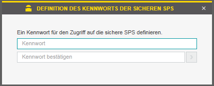
 - When initially writing a project to this Safety PLC: the 'Safety PLC Password Definition' dialog appears where you have to define and confirm a password.
If a password already exists (see step 4) but you are not yet logged on to the Safety PLC: the 'PLC Authentication' dialog appears. Enter the Safety PLC password and click 'OK'. Refer to the topic "Safety PLC Password protection" for further information.Note
A secure password is one that has not been shared or distributed to any unauthorized personnel and does not contain any personal or otherwise obvious information. Furthermore, a mix of upper and lower case letters, numbers and special characters offers the best security possible. You should choose a password length of at least 6 characters. The password is case-sensitive and can be a mix of up to 64 characters. - A warning message appears informing you that the safety-related application will not be available during the following transfer operation with the subsequent Safety PLC start-up/restart. Therefore, no safety-related requests from the application can be processed during the start-up phase.
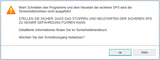
Confirm the message with 'Yes' to continue the 'write and start' procedure.WARNINGUnintended machine operation - Prior to writing the safety-related image and starting up the Safety PLC, make certain that the temporary absence of the safety-related application and therefore the downtime of the entire safety installations, cannot result in any hazardous situations.
- Do not enter the zone of operation while the Safety PLC is starting up.
- Ensure that no other persons can access the zone of operation while the Safety PLC is starting up.
- Use appropriate safety interlocks where personnel and/or equipment hazards exist.
- On the Safety PLC, the project is automatically stored as Boot Project in the Flash Memory. As a result, the Safety PLC will automatically execute this project after each start-up.Following the successful file transfer, the Safety PLC restarts, loads the safety-related project, and initializes accordingly. As mentioned, the safety-related application will not be available during this phase. Then, the Safety PLC automatically starts executing the safety-related application. The status 'Safe Run' is displayed in the Safety Cockpit.In PLCnext Engineer, the monitoring mode is automatically activated as soon as the safety-related application is executed. Therefore, the 'Monitor Mode' button appears pressed in the Safety Cockpit:

- Perform a function test after the successful Safety PLC startup. To support you in this, PLCnext Engineer provides the following features:
- Monitoring mode in which online values are read cyclically from the Safety PLC and displayed in the editors (already active after the successful file transfer and Safety PLC startup).The monitoring mode is considered as safety-related mode as the execution of the application cannot be influenced by debug commands.
- Debug mode which provides debug commands, such as forcing/overwriting of variables and single cycle operations of the Safety PLC. The debug mode includes the monitoring mode, i.e., also online values are visible in the editors.Debug mode is considered as non-safety-related because you can influence the execution of the program by forcing/overwriting variables.
- WATCHES window for collecting variables from different worksheets, displaying their online values (in monitoring mode) and execute debug commands (in debug mode).
If you detect incorrect behavior or an error in the safety-related application logic during the function test, you must make certain that it will not lead to a hazardous situation. Observe the safety warning message noted at the beginning of this topic. Next, remove the error in the application logic by reediting the project. Following a successful compilation, start commissioning again.Note
The test of the application in debug mode using debug commands and the WATCHES window may not replace the proper function test using I/O devices/sensors/actuators under any circumstances. The test in debug mode may only be performed in addition to the standard function test, as a preliminary test, for example.
| Note
After the modification of safety-related parameters: If you have changed safety-related parameters (such as F-parameters or channel-related parameters), you have to write additionally the standard project to the standard controller. If only the Safety PLC is updated, Profinet cannot become operational. Refer to the topic "Safety Parameters Editor", section "After a safety parameter modification" for details. |
| Note
After writing a project to the Safety PLC, it is recommended to document the CRCs that are shown in the 'Safety Information' editors of the 'Project' node (PLANT) and of each safety-related user POU (COMPONENTS). These checksums are, for example, relevant if you want to compare this version with a future project version at a later time. Refer to the topic "Project Comparison" for further information. |
Safety PLC simulation: optional addition to the function test
PLCnext Engineer additionally provides a function for simulating the safety-related application, which you can use to test the behavior of the application logic fully independently of the real hardware. Simulation mode offers the same debug commands too.