SF_Reset
Help version 1.1 / Issue date: 2018.03
The following description is valid for the function block SF_Reset_V1_0z, Version 1.0z (where z = 0 to 9).
|
Short Description
| The SF_Reset function block provides a manual reset function. The reset signal at the ResetOut output takes place as a short TRUE pulse with a length of one cycle of the Safety PLC, if a manual reset is requested at the ResetIn input.
Note
Although contained in the safety-related PLCopen_SF library, the SF_Reset FB is a standard (non-safety-related) function block with standard input and output formal parameters. |
The reset request is triggered by the operator by means of a connected control device (e.g., a button). Function block inputs are available to specify whether a rising or a falling edge (according to EN ISO 13849-1) is evaluated at the ResetIn input.
In addition, when evaluating the falling edge, the duration of the request signal can be monitored.
The request signal at the ResetIn input is only evaluated if the OperationStop input signals that the system is in operation stop mode. |
|
Block Icon
| 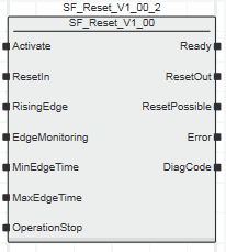 |
|
Inputs
|  Activate Activate
| Short description | Value |
State-controlled input for activating the function block. Data type: BOOL
Initial value: FALSE |
-
FALSE: Function block inactive.
-
TRUE: Function block activated.
|
Refer to the topic "Activate" for details.
ResetIn
| Short description | Value |
Edge-triggered input for the request "manual resetting".Data type: BOOL
Initial value: FALSE | Which signal edge is evaluated depends on the value applied to the RisingEdge input.
- Edge TRUE > FALSE: Manual resetting by a falling edge according to EN ISO 13849-1
- Edge FALSE > TRUE: Manual resetting by a rising edge
|
Refer to the topic "ResetIn" for details.
RisingEdge
| Short description | Value |
State-controlled input for specifying which signal edge is evaluated at the ResetIn input.Data type: BOOL
Initial value: FALSE |
-
FALSE: Evaluation of the falling edge (according to EN ISO 13849-1)
-
TRUE: Evaluation of the rising edge
|
Refer to the topic "RisingEdge" for details.
EdgeMonitoring
| Short description | Value |
State-controlled input for whether the duration of the request signal at the ResetIn input is to be monitored.Data type: BOOL
Initial value: FALSE |
-
FALSE: No monitoring
-
TRUE: Monitoring of the request signal at the ResetIn input in terms of its minimum and maximum duration
Note
The EdgeMonitoring parameter must only be set to TRUE if the parameter RisingEdge = FALSE (falling edge) |
|
Refer to the topic "EdgeMonitoring" for details.
MinEdgeTime
| Short description | Value |
| Input for specifying the minimum duration of the request signal at the ResetIn input in seconds.Data type: TIME
Note
The MinEdgeTime input is only evaluated when input EdgeMonitoring = TRUE. |
| Initial value: 0.5 s
Minimum value: 0.1 sEnter a time value according to your risk analysis. |
Non-conformance to safety function requirements
- Verify that the time value set at the time input corresponds to your risk analysis.
- Be sure that your risk analysis includes an evaluation for incorrectly setting the time value at the time input.
- Validate the overall safety-related function with regard to the set time value and thoroughly test the application.
|
Refer to the topic "MinEdgeTime" for details.
MaxEdgeTime
| Short description | Value |
| Input for specifying the maximum duration of the request signal at the ResetIn input in seconds.
Note
The time at the MaxEdgeTime input must be higher than the time at the MinEdgeTime input. |
Note
The MaxEdgeTime input is only evaluated when Input EdgeMonitoring = TRUE. |
| Initial value: 2 s
Minimum value: 0.1 sEnter a time value according to your risk analysis. |
Non-conformance to safety function requirements
- Verify that the time value set at the time input corresponds to your risk analysis.
- Be sure that your risk analysis includes an evaluation for incorrectly setting the time value at the time input.
- Validate the overall safety-related function with regard to the set time value and thoroughly test the application.
|
Refer to the topic "MaxEdgeTime" for details.
OperationStop
| Short description | Value |
State-controlled input for signaling the operation stop of the standard PLC.Data type: BOOL
Initial value: FALSE |
-
FALSE: System is not in the operation stop mode
-
TRUE: System is in operation stop mode
|
Refer to the topic "OperationStop" for details.
|
|
Outputs
| Ready
| Short description | Value |
| Output for signaling "Function block activated/not activated".Data type: BOOL |
-
FALSE: Function block is not activated (Activate = FALSE) and all outputs of the function block are switched to FALSE/SAFEFALSE.
-
TRUE: Function block is activated (Activate = TRUE) and the output parameters represent the state of the safety-related function.
|
Refer to the topic "Ready" for details.
ResetOut
| Short description | Value |
| Output for the function block reset signal (pulse with a length of one cycle of the Safety PLC).Data type: BOOL |
-
No pulse:
- No request for reset at the ResetIn input
-
or no valid signal duration of the request signal at the ResetIn input (only with configured monitoring, see EdgeMonitoring input)
-
or system is not in the operation stop mode (input OperationStop = FALSE)
-
or the function block is not activated
-
or an error message is present (Error = TRUE).
-
Pulse is output:
- Reset request at the ResetIn input
-
and valid signal duration at the ResetIn input (only with configured monitoring, see EdgeMonitoring input)
-
and system is in operation stop mode (input OperationStop = TRUE)
-
and the function block is activated
-
and the function block detects no error.
|
Refer to the topic "ResetOut" for details.
ResetPossible
| Short description | Value |
| Output for signaling reset request is possible or not. Data type: BOOL |
-
FALSE: reset request is not possible, as...
- system is not in the operation stop mode (input OperationStop = FALSE)
-
or the function block is not activated
-
or an error message is present (Error = TRUE).
-
TRUE: reset request is possible, as...
- system is in operation stop mode (OperationStop = TRUE)
-
and the function block is activated
-
and the function block detects no error.
|
Refer to the topic "ResetPossible" for details.
Error
| Short description | Value |
| Output for error message.Data type: BOOL |
-
FALSE: No error is present.
-
TRUE: The function block has detected an error. The ResetOut output switches to FALSE as a result.
|
Refer to the topic "Error" for details.
DiagCode
| Short description | Value |
| Output for diagnostic message.Data type: WORD | Diagnostic message of the function block.
The possible values are listed and described in the topic "Diagnostic codes". |
Refer to the topic "DiagCode" for details.
|
| Detailed information | Signal sequence diagram
The two following diagrams show the basic signal behavior of the function block if parameterized for the evaluation of the rising edge (RisingEdge = TRUE) and if parameterized for the evaluation of the falling edge (RisingEdge = FALSE).
Assumption:
-
OperationStop = TRUE: The system is in operation stop mode. Thus ResetPossible = TRUE, i.e., the reset request by the operator is possible.
- There is no monitoring of the duration of the request signal parameterized, i.e., input EdgeMonitoring = FALSE.
| Parameterizing for the rising edge (RisingEdge = TRUE) | Parameterizing for the falling edge (RisingEdge = FALSE) |
 |  |
| 0 | The function block is not yet activated (Activate = FALSE). As a result, all outputs are FALSE. |
| 1 | The function block has been activated (Activate = TRUE). |
| 2 | The operator triggers the control device for the manual resetting (Edge FALSE > TRUE at the ResetIn input).If the evaluation of the rising edge (RisingEdge = TRUE, see left diagram) is parameterized, a defined pulse is applied to the ResetOut output as reset signal. The falling edge of the request signal is then no longer evaluated. |
| 3 | The operator releases the control device for the manual resetting (Edge TRUE > FALSE at the ResetIn input).If the evaluation of the falling edge (RisingEdge = FALSE, see diagram on the right) is parameterized, a defined pulse is applied to the ResetOut output as reset signal. |
Application example
This example illustrates the SF_Reset function block with a subsequent safety-related SF_EmergencyStop function block. The ResetOut output of the SF_Reset function block is connected to the Reset input of the SF_EmergencyStop function block in order to control resetting there.
Both function blocks are permanently activated by the TRUE constants at the Activate inputs. The SF_Reset function block is parameterized for the evaluation of the falling edge.
The S2 reset button is connected as control device for the manual resetting to input terminal 3.1 of the PSDI. The assigned global I/O variable S2_Reset in turn is connected to the ResetIn input of the SF_Reset function block.
Note
The OperationStop input evaluates the state of the standard PLC in terms of the operation stop.
The ResetPossible output signals whether a manual resetting is possible. It is connected to a terminal of an output device for signaling purposes. Connect the ResetPossible output to a signal lamp, for example. |

Function block instantiation
The IEC 61131-3 standard defines function block instantiation. Instantiation means, a function block is defined once and can be used (instantiated) several times. This applies to all standard and safety-related FBs (local POUs as well as firmware and user library FBs).
Why instantiation?
A function block has an internal memory where it stores its own processing data (local variables). As a consequence, the output values calculated by the FB depend on the internally stored values. The same input values applied to an FB instance do not necessarily deliver the same results in another FB instance.
Therefore, it is necessary to store the internal data of the FB to a separated memory area each time the function block is processed, i.e., for each FB instance. To uniquely identify each FB instance and to clearly separate its memory area, instance names are used. The instance name of a function block has to be declared in the 'Variables' table of the POU where the FB is going to be used.
The following applies:
- Function blocks can be instantiated in other function blocks or in program POUs. Calling FBs in function POUs is not possible.
- Functions are called without instantiation because they do not have an internal memory.
Safety-related and standard (non-safety-related) code is strictly distinguished in PLCnext Engineer. If a Safety PLC is included in your project, the following applies:
- Safety-related FBs can only be instantiated in safety-related POUs but not in standard (non-safety-related) POUs.
- User-defined standard FBs can only be instantiated in standard POUs. They cannot be called in safety-related POUs.
- Particular standard firmware FBs can be instantiated in both safety-related and standard POUs.
Note
When inserting a standard FB into a safety-related SNOLD network, the rules for implicit type conversion (safety-related to standard) apply. |
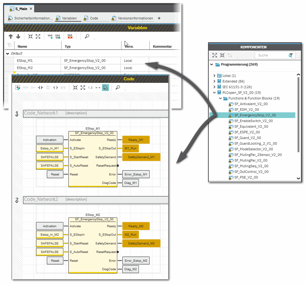
Example for the instantiation of a safety-related PLCopen function block
The safety-related PLCopen function block 'SF_EmergencyStop_V2_00' was inserted into the project via a library. It is then available in the 'Programming' category of the COMPONENTS area. There is a folder with the same name as the library that provides the FBs for insertion into the safety-related code.
The FB is to be called twice in the code of the safety-related program 'S_Main' to evaluate the status of two safety-related emergency stop command devices. For each FB instance, an instance name is declared in the 'Variables' table of the calling program: EStop_M1 and EStop_M2. The FB instances have been inserted into the code worksheet, each instance with different variables connected to its input and output formal parameters.
Additional information is available in the following sections:
|