| 1 | Project creation
Create a new project, by selecting
- a controller-based template on the Start Page.
- by selecting an example project template for your controller on the Start Page.
- the command 'File > New Project'. This command creates and empty project with an empty PLANT.
|
| 2 | PLANT structuring
Model your application in the PLANT by inserting devices. This can, for example, be done by scanning the network or using the station editor of existing devices in PLANT.
 Example: scanning when starting with a controller-related template Example: scanning when starting with a controller-related template
Note
For a network scan as described below, it is not necessary to manually establish a communication connection using the 'Connect' command (controller context menu in the PLANT) before the scan. This is done automatically by PLCnext Engineer. |
- Double-click the 'Project' node.
In the editors area, open the 'Online Controllers' editor (see (1) in the figure below).In the devices list, the name of the controller contained in the PLANT is already entered on project side ('Name of station (Project)'). However, it is not yet assigned to a physical device in the network.
Note
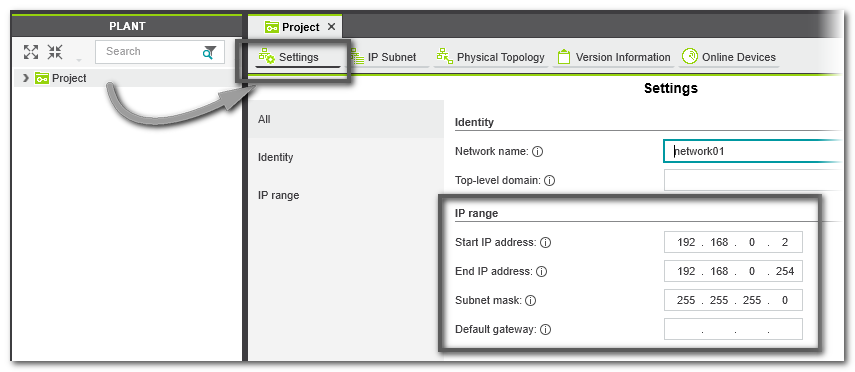
The IP address entered on project side is derived from the IP address range of the current project as set in the 'Ip subnet' category in the 'Settings' editor of the 'Project' node. |
- In the drop-down list (2), select the LAN adapter of your computer which is connected to the controller network to be scanned.
- Click the 'Scan the network' button (3) on the 'Online Controllers' toolbar.
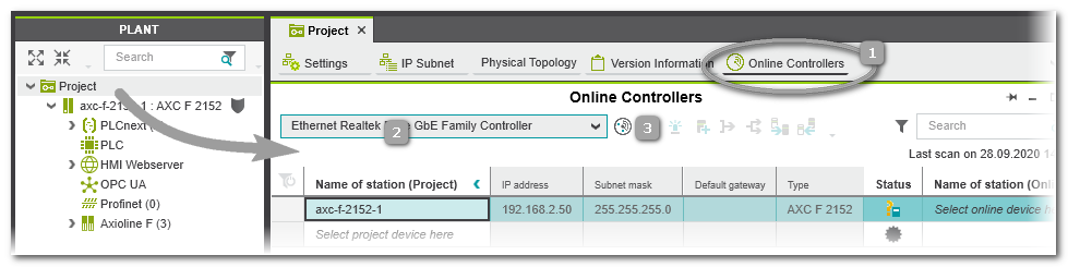 The network is scanned and found controller devices are listed in the table. The network is scanned and found controller devices are listed in the table.
- Assignment of project device and online device:The behavior is different, depending on whether the controller names on project side and online side are the same or different.
- If the name of the found online controller does not match the controller name used in the project (PLANT node 'Project'), the project controller and the online controller are listed in different table lines.
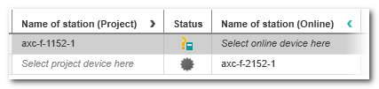 In this case, open the drop-down list 'Name of station (Online)' in the table line with the controller specified in the PLANT. Select the identifier of the scanned controller to assign it to the project station name. In this case, open the drop-down list 'Name of station (Online)' in the table line with the controller specified in the PLANT. Select the identifier of the scanned controller to assign it to the project station name.
Note
Alternatively, you can assign a controller device listed in the PLANT tree to the scanned controller by selecting a project device from the drop-down list 'Name of station (Project)'. |
- If the project controller name and the online controller name are identical, the assignment is made automatically after scanning.
Note
If the controller device includes a Safety PLC and you are not logged on to the Safety-related Area, you first have to enter the password for accessing the Safety-related Area. If this is the first edit operation of safety-related data in the current project, you are now prompted to define a password. |
- After the project and the online device have been assigned, the communication connection 'Status' may switch to 'Warning' because the communication settings of the scanned controller do not match the (default) communication settings in your project (which are predefined in the used project template).
 In this case, proceed as follows: In this case, proceed as follows:
Select the table line of the controller with 'Warning' status and execute the command 'Apply the online device settings to the project device settings' (context menu or toolbar button):
 The communication settings configured in the scanned controller are transferred to the project. The communication settings configured in the scanned controller are transferred to the project.
Note
After reading the IP address from the scanned controller, an error message may be output that the IP range configured in your project does not match the read IP address. Open the 'Settings' editor of the 'Project' node and adapt the IP range in the 'Ip subnet' category accordingly. |
Example: scanning Profinet devices
Note
For a network scan as described below, it is not necessary to manually establish a communication connection before the scan. This is done automatically by PLCnext Engineer. |
- Double-click the 'Profinet' node.
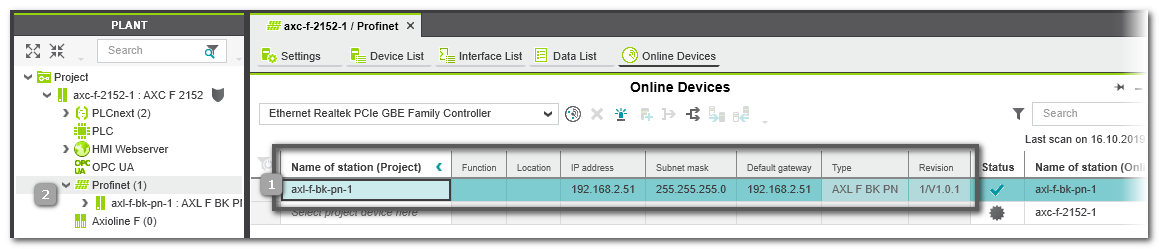
In the editors area, open the 'Online Devices' editor (see (1) in the figure below).
- In the drop-down list (2), select the LAN adapter of your computer which is connected to the controller network to be scanned.
- Click the 'Scan the network' button (3) on the 'Online Devices' toolbar.
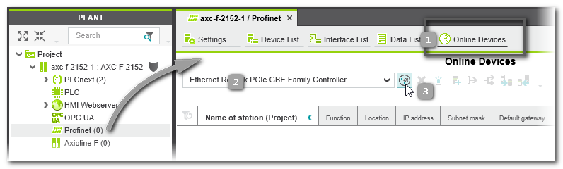 The network is scanned and found Profinet devices are listed in the table. The network is scanned and found Profinet devices are listed in the table.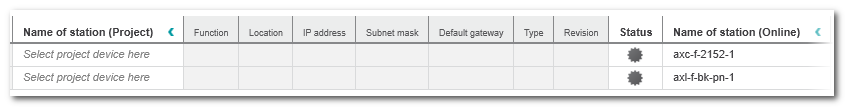
Note
If your project controller can be used as both the Profinet controller and Profinet device at the same time, the controller is also found as device and listed in the table (as shown in the example above). |
The columns left of the 'Status' column represent the configuration edited in the project. The columns are empty as no Profinet device has yet been added to the project.The  icon in the 'Status' column indicates that the scanned device is not yet contained in the project. icon in the 'Status' column indicates that the scanned device is not yet contained in the project.
- Select the table line with the found device and execute the command 'Add to Project' from the context menu or click the following toolbar button:
 If a scanned device cannot be uniquely identified because, for example, more than one matching device type is available in the COMPONENTS area ('Device' or 'References' category), the 'Station structure preview' dialog appears. In the dialog, select the 'Type' of the scanned device from the drop-down list and confirm to continue. If a scanned device cannot be uniquely identified because, for example, more than one matching device type is available in the COMPONENTS area ('Device' or 'References' category), the 'Station structure preview' dialog appears. In the dialog, select the 'Type' of the scanned device from the drop-down list and confirm to continue.
Note
Only add a controller as Profinet device if it is not the project controller. Otherwise, the controller would be used as its own child element. |
- After adding the device to the project, the communication connection 'Status' may switch to 'Warning' because the communication settings of the scanned device do not match the (default) communication settings in your project.In this case, proceed as follows:
Select the table line of the device with 'Warning' status and execute one of the following commands from the context menu or click the related toolbar button:
- Command 'Apply the online device settings to the project device settings' or toolbar button:
The communication settings configured in the scanned device are transferred to the project. The 'Online Devices' table is updated accordingly on project side. The 'Status' of the communication connection between PLCnext Engineer and the device is set to 'OK' (green). See (1) in the figure below.
Note
After reading the IP address from the scanned device, an error message may be output that the IP range configured in your project does not match the read IP address. Open the 'Settings' editor of the 'Project' node and adapt the IP range accordingly. |
- Command 'Apply the project device settings to the online device settings' or toolbar button:
 The communication settings configured in the project are transferred to the scanned device. The 'Online Devices' table is updated accordingly on online side and the communication status is set to 'OK'. The communication settings configured in the project are transferred to the scanned device. The 'Online Devices' table is updated accordingly on online side and the communication status is set to 'OK'.
The device is added as node in the PLANT using its configured device name (2).
Profinet I/O modules which are connected to this device are also inserted below the device node.
Example:
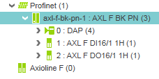
Double-clicking the Profinet device node opens the properties providing the 'Module List' editor. In this table, all found Profinet I/O modules are listed.
Additional methods for scanning devices are described in the help chapter "Online: Scan Network to add Devices to PLANT".
It is also possible to insert devices via the station editors. Refer to topic "Offline: Add Devices manually to PLANT" for detailed information. |
| 3 | IP configuration
Define the IP settings for the devices in the PLANT. If you work online, i.e., you have scanned the network, you can modify the IP settings of scanned devices directly in the 'Online Devices' editor as shown in the first example below. If you work offline and you have structured the PLANT via the station editors, the IP settings are assigned according to the IP range set for the 'Project' node. You can then modify them via the 'Settings' editor of each device (see second example procedure below).
Example: read IP configuration from scanned devices via the 'Online Devices' editor
IP settings of scanned device
If you want to modify the IP address of the scanned device, or if an error message appears in the MESSAGES window (category 'Error list'), informing you that the scanned IP address does not match the IP range set for the project, you have the following possibilities:
- Adapt the IP range of the project in the 'Settings' editor of the 'Project' node accordingly so that it includes the IP address of the scanned device. The same applies to the subnet mask and gateway settings.Double-click the 'Project' node and open the 'Settings' editor.
- Modify the IP settings of the scanned device directly in the 'Online Controllers' editor (for contollers, 'Project' node) or 'Online Devices' editor (for Profinet devices, 'Profinet' node) where you have performed the network scan. When modifying a field in the left part of the table (on project side) and confirming the modification with <Enter>, the new setting is automatically written to the device (shown on online side).Example: modifying the IP address of a scanned AXC F 2152 controller in the 'Online Controllers' editor of the 'Project' by overwriting the current value and pressing <Enter>.
Note
A Safety PLC integrated in a controller device does not have an own IP address. |
Example: define the IP configuration via the 'Settings' editor
When inserting a controller or bus device into the PLANT manually, an IP address within the specified project IP range is automatically assigned (provided that an address is free). In the most cases, the automatically assigned address in the project will not match the current IP address configuration on the device (which is either the preset IP address after unboxing/resetting the device or an already configured address). The IP settings in the project can be adapted to the IP settings on the hardware.
- In the PLANT, double-click the device node to open its properties.
- Open the 'Settings' editor and select the parameter category 'Ethernet'.
- Enter the desired IP settings and confirm each setting with <Enter>.Observe that the entered individual IP address is within the specified project IP range. Otherwise, a corresponding error message appears in the MESSAGES window, category 'Error list'.
|
| 4 | Device parameterization
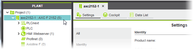
Parameterize the devices in the PLANT. For that purpose, double-click each device node in the PLANT to open its properties in the editors area. To parameterize safety-related devices, you have to be logged on to the Safety-related Area.
Example
|
| 5 | Add Libraries or Import IEC Types
If required:
- In the 'Libraries' category of the COMPONENTS area, add libraries providing
- IEC 61131-3-compliant POUs
- non-IEC 61131-3 programs (only with PLCnext Technology controllers)
- devices
- or HMI symbols
-
(IEC 61131-3-compliant POUs and data types as well as HMI symbols)
- from another PLCnext Engineer project, or
- from a PLCopen-compliant XML file (schema version 1.01 or newer).
Types imported with one of these methods are added to the 'Local' folder in the respective category in the COMPONENTS area.
|
| 6 | Application code development
- Create POUs in the respective category in the COMPONENTS area:
'Programming > Local > Programs' and 'Functions and Function Blocks'.
Object-oriented function blocks with methods are supported.
- Define data types (folder 'COMPONENTS | Programming > Local > Data Types').
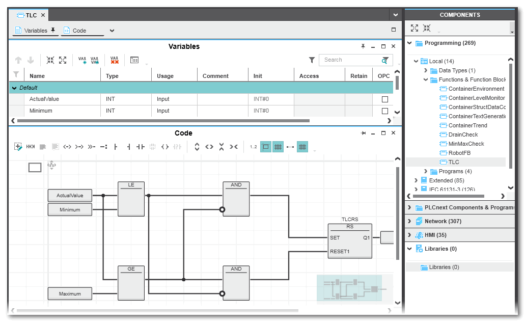
- Program the POUs in one of the IEC 61131-3 programming languages FBD/LD, ST or SFC. Safety-related code has to be written in SNOLD code worksheets. For that purpose, you have to be logged on to the Safety-related Area.
- With a PLCnext Technology controller, you can declare IN and OUT ports in program POUs instead of or in addition to resource-global variables. Via these ports, communication is possible with non-IEC 61131-3 programs you have included as libraries. See section "Integrating externally developed non-IEC 61131-3 programs ..." for details.
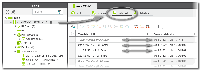
- Assign global IEC 61131-3 variables to process data items. By defining this mapping, the application is able to read input and write output terminals. The assignment can be done in the Data List editors of, for example, the 'IEC 61131-3' node or I/O device involved.With a PLCnext Technology controller, IN and OUT ports can be assigned to each other in the Port List of the 'PLCnext' node. This also includes ports provided by non-IEC 61131-3 programs you have included as libraries.If a Safety PLC is included, you can create exchange variables which enable the communication with the standard (non-safety-related controller).
Example: POU in FBD
Example: Assignment of global variables to process data items in the controller Data List
|
| 7 | Task scheduling and program instantiation
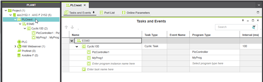
- Double-click the 'PLCnext' node in the PLANT and open the 'Tasks and Events' editor.
- Insert and configure tasks and events.
- Instantiate programs to be run in the defined tasks.PLCnext Technology controllers can also execute non-IEC 61131-3 programs.
Example for a PLCnext Technology controller
Note
If a Safety PLC is included in your project, the PLCnext 'Tasks and Events' editor contains a SafetyProxyTask which has been created automatically. This SafetyProxyTask triggers the execution of the Safety PLC. This task cannot be edited or deleted.
Refer to the topic "Safety PLC Runtime Configuration" for details. |
|
| 8 | HMI application design
- Insert at least one HMI page in the PLANT.
- Design the HMI page(s) by inserting HMI objects via drag & drop from the COMPONENTS
area.
- Create HMI tags for global IEC 61131-3 variables and assign these HMI tags to dynamic properties of HMI objects. By defining this mapping, the objects on the HMI page(s) can be animated (depending on variable/process data item values) and they can control the application as they can write variables (markers and outputs). HMI tags can be created in the Data List editor of the 'IEC 61131-3' node.
The following assignment of an HMI tag to a dynamic property is to be done in the properties editor of the respective HMI object/symbol.
|
| 9 | OPC UA configuration
PLCnext Technology controllers include an
OPC UA Server
which is integrated in the controller besides the controller runtime.
In addition, PLCnext Technology controllers with a firmware version 22.0 or newer support the OPC UA PubSub (publisher/subscriber) communication model.OPC UA-related settings can be done in the editors of the 'OPC UA' PLANT tree node. |
| 10 | Application Startup
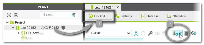
- Execute the 'Write and Start' command to build the project image (compile the project), write it to the controller and run the application. The 'Write and Start' command is available in the context menu of the controller node (PLANT) and in the 'Cockpit' editor. To open the 'Cockpit', double-click the controller node in the PLANT and click 'Cockpit' in the editors area.
 Alternatively, run the project on the integrated simulation (if available for the controller type used). This allows you to test the behavior of the application logic without connected controller. Refer to the topic "" for detailed information.Typical programming errors are detected by the automatic background check. (Note that the
error list
is only updated after completing the compilation.) Using the command 'Project > Rebuild' you can additionally build the entire project (e.g., for eliminating programming errors) without writing it to the controller. Alternatively, run the project on the integrated simulation (if available for the controller type used). This allows you to test the behavior of the application logic without connected controller. Refer to the topic "" for detailed information.Typical programming errors are detected by the automatic background check. (Note that the
error list
is only updated after completing the compilation.) Using the command 'Project > Rebuild' you can additionally build the entire project (e.g., for eliminating programming errors) without writing it to the controller.
- Use the monitoring and debugging tools for performing a function test.
Further Info
Refer to chapter "" for details. |
|
| 11 | Safety-related Application Startup
If a Safety PLC is included in your project, it has to be controlled completely independent of the standard (non-safety-related) controller. For that purpose an own 'Safety Cockpit' is provided. Here, you have to perform the same steps as for standard controller:
- 'Write and Start' the safety-related application to the Safety PLC (in the Safety Cockpit or via context menu of the Safety PLC).
- Use the monitoring and debugging tools for performing a function test.
|