Drawing and Editing Paths
Paths consist of a collection of points and straight line segments or curve segments (so-called Bezier curves). The HMI editor allows you to insert paths into the HMI page either by using the standard HMI objects 'Polycurve Path' and 'Polyline Path' or by converting objects, such as an ellipse, a rectangle or a straight line to a path.
Paths are edited by double-clicking the path object in the HMI page or by selecting the command 'Edit Shape of Path' from the context menu of a path.
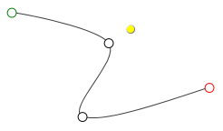
While editing a path, the points on it are shown with different colors: green represents the start point of the path, red is the end point, and black are segment points. Note that the yellow
dot (see the following figure) is not a segment point but represents the rotation center of the path.
By dragging a point, the shape of the path can be edited. The context menu of a path in edit mode provides all commands that can be used to edit the path, e.g., to add/delete segments, open/close a path, etc.
The edit mode is exited by clicking anywhere in the HMI page or by right-clicking a point on the path and selecting 'Exit Path Edit' from the context menu.
In selection mode (edit mode is deactivated), path objects can be moved, sized, rotated, etc., like standard objects. Refer to the topic "Editing Objects".
What do you want to do?
 Draw a polycurve or polyline path
- In the 'Objects' group under the 'HMI' category, select the 'Polycurve Path' or 'Polyline Path' object.
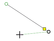
- On the HMI-page, left-click on the start point of the object.
- Draw a segment and click to complete the segment. When you click to complete a segment, a new segment is automatically started. Repeat this step for each segment.
- Press <Esc> or right-click anywhere in the HMI page to complete the object.
If you want to add further line segments to a path once you have exited the edit mode, activate the edit mode by double-clicking the path and then right-click the starting or end point of the path and select 'Begin Draw Mode' from the context menu.
Edit a path
Activate the edit mode by double-clicking the path or selecting 'Edit Shape of Path' from the context menu of the path.
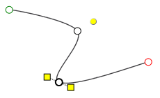
To change the shape of the path, select a point and drag the point or the yellow handles of the point.
Use the context menu commands available for a selected line or a selected point to
- add new line or Bezier curve segments to the path. This splits the selected segment into two segments.
- delete the selected segment.
- convert the selected line segment to a Bezier curve or vice versa (i.e., change a straight segment to a curved segment and vice versa).
- delete the selected point. (The start point cannot be deleted.)
- open or close the path. The 'Close Path' command adds a straight line segment between starting and end point. The 'Open Path' command separates the selected point into a start and end point. Both commands are only available in the context menu if the starting or end point is selected.
- convert the curve at the selected point between smooth and corner (only available if a point is selected).
Convert an object to a path
To convert the standard HMI objects 'Line', 'Ellipse' and 'Rectangle' to a path, right-click the object(s) and select 'Convert to Path' from the context menu. The newly created paths are handled like standard paths.
Create a new path by combining several objects (shapes)
Select the objects (single paths, lines, ellipses and rectangles) in the HMI page, right-click the selection and choose one of the shape modes described in the following table from the 'Combine Shapes' context menu.
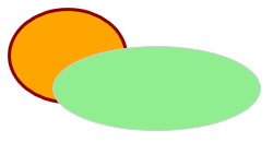
For the descriptions of the various shape modes, the following original shapes (2 ellipses objects) serve as an example.
| Shape mode | Description | Combined shapes |
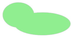
| Unite | Merges the shapes into one shape.The new shape takes on the visual properties such as the background fill, the line color and width, etc., from the shape selected last.
Note
The newly created shape cannot be converted back to the original shapes (see the 'Assemble' shape mode below). |
|  |
| Exclude Intersection | Merges the shapes into one shape with the intersection area of the shapes omitted (observe the note above).The new shape takes on the visual properties such as the background fill, the line color and width, etc., from the shape selected last.The resulting shape can be converted back into the original shapes with the 'Combine Shapes > Disassemble' command from the context menu of the shape. | 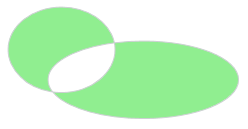 |
| Intersect | Creates a new shape from the intersection area of the selection. The area outside the intersection is removed (observe the note above).The new shape takes on the visual properties such as the background fill, the line color and width, etc., from the shape selected last. |  |
| Subtract | Cuts out (subtracts) the area of the last selected shape from the shape selected first (observe the note above). | 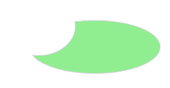 |
| Assemble | Combines the shapes into a single shape while keeping each original shape.The new shape takes on the visual properties such as the background fill, the line color and width, etc., from the shape selected last.The combined shape can be converted back into the original shapes with the 'Combine Shapes > Disassemble' command from the context menu of the shape. | 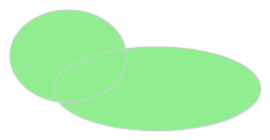 |