HMI Quickstart
In this Quickstart, you will learn how to create an HMI application, write the project including the HMI application to the controller and visualize/write the variable you have created in PLCnext Engineer using a standard web browser.
In this tutorial, you will create 2 HMI pages. On the first page (startup page), you will insert a button used to navigate to the second HMI page when pressing it. On the second page, a radial gauge will visualize the value of the global IEC 61131-3 variable 'RealVar'. The 'Reset' button will reset the 'RealVar' value to 0.
Prerequisite for this Quickstart:- When executing the HMI application on the controller: the Quickstart project is created with a valid hardware configuration (IP settings).
- When executing the HMI application on the controller: the controller is reachable in the network so that the project can be written and started.
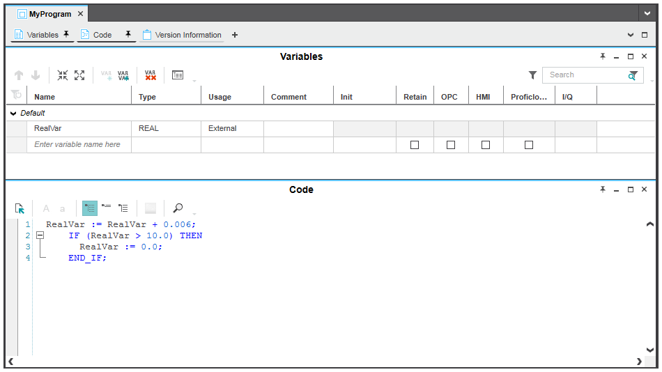
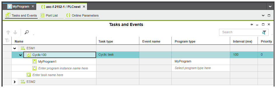
- A program POU in Structured Text is available and the program instance is assigned to a cyclic task as shown below.
The Quickstart uses the following program code written in Structured Text (ST).
You can copy this ST code to the code worksheet.
| RealVar := RealVar + 0.006; IF (RealVar > 10.0) THEN RealVar := 0.0; END_IF; |
 Program and variable declaration used
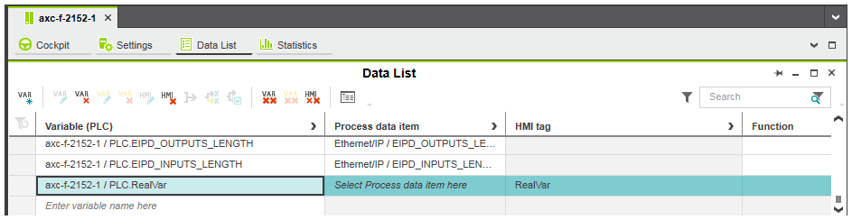
Step 1: Assign global IEC 61131-3 variables to HMI tags
The variable to be visualized must be assigned to an HMI tag. The HMI tag will later be linked to the path dynamic of the radial gauge needle and the 'Write value' action of the 'Reset' button.
- In the PLANT, double-click the controller node.
- In the editors area, open the 'Data List' editor.
- In the 'Data List' table, right-click into the 'HMI tag' cell of the 'RealVar' variable and select 'Add HMI Tag' from the context menu. The created HMI tag name 'RealVar' is derived from the variable name.
| Note
Regarding their use in HMI pages, the following applies to variables of the Safety PLC:
|
Step 2: Add HMI pages to your project
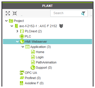
We need 2 HMI pages for this Quickstart. We will name the pages 'Home' and 'PathAnimation'.
- To add an empty HMI page to the current project, right-click the 'Application' node under the 'HMI Webserver' node in the PLANT and select 'Add HMI Page' from the context menu.
- Rename the page to 'Home' by selecting the node, pressing <F2> and typing the name.
- Repeat these steps for the second HMI page 'PathAnimation'.
- To designate the HMI page 'Home' as startup page (the startup page will be loaded first when the visualization is started), right-click the node in the PLANT and select 'Set HMI Page as Startup' from the context menu.
Step 3: Design the HMI pages by inserting objects
You can now insert the graphic objects into the HMI pages. The following objects are used:
- a 'Button' named 'Path Animation' that will load the second HMI page when pressed.
- an included 'Radial Gauge' symbol that displays the current value of the variable 'RealVar' to be visualized.
- a 'Button' named 'Reset' that will write the value 0 to the 'RealVar' variable.
'Button' for navigation to the second page
- Double-click the 'Home' page under the 'HMI Webserver | Application' node in the PLANT to open the page in the editors area.
- In the COMPONENTS area under the 'HMI' category, open the 'Objects' group and select the 'Button' object.
- Drag the 'Button' object using the mouse into the page and drop it at the desired position. Alternatively, select the object in the 'Objects' group, move the cursor into the HMI page and left-click into the page.
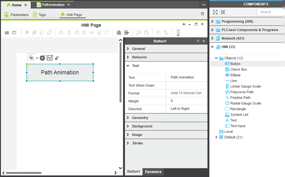
- Select the 'Button' object in the HMI page and enter the text 'Path Animation' for the 'Text' property in the properties window (located on the right in the HMI page). Alternatively, double-click the button, enter the label and click anywhere in the HMI page.Resize the button to fit the text by dragging an object handle.
Included 'Radial Gauge' symbol for the visualization of the global variable
PLCnext Engineer is shipped with a number of included symbols. With these included symbols you can create your HMI pages, and control/visualize your processes out of the box. These symbols can be found in the 'Default | Symbols' folder in the COMPONENTS area under the 'HMI' category.
- Double-click the 'PathAnimation' page under the 'HMI Webserver | Application' node in the PLANT to open the page in the editors area.
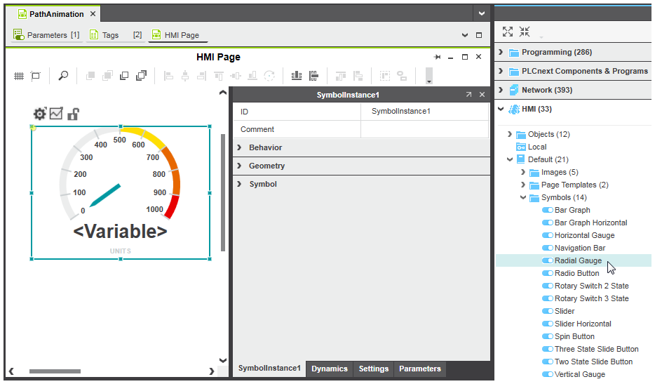
- In the COMPONENTS area under the 'HMI' category, open the 'Default | Symbols' folder and select the 'Radial Gauge' symbol.
- Drag the symbol using the mouse into the page and drop it at the desired position.
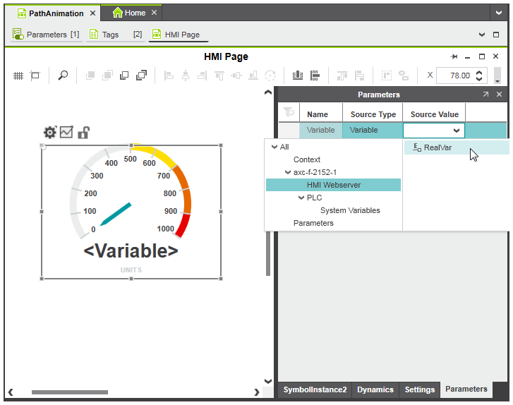
- Now we have to link the gauge scale to the HMI tag 'RealVar' to display the current value of the variable 'RealVar' that we want to visualize.Select the 'Parameters' tab in the properties window of the symbol.
- In the 'Source Value' list box, select the 'HMI Webserver' entry in the tree on the left and then the HMI tag 'RealVar' on the right by clicking it and pressing anywhere outside the list box or pressing <Enter>.
'Button' for writing the global variable
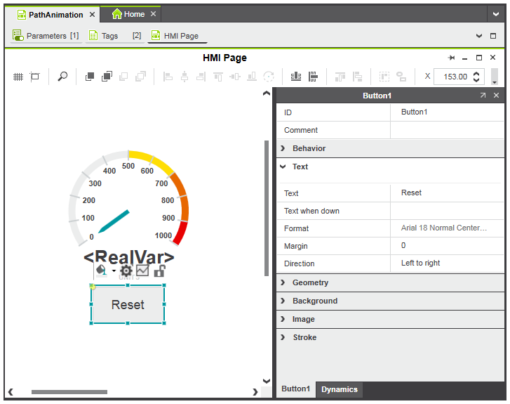
- In the 'PathAnimation' page, insert a 'Button' object as described above.
- Double-click the button in the HMI page, enter the label 'Reset' and click anywhere in the HMI page.
Step 4: Add dynamics
We will now add the following dynamics to the properties of the objects:
- 'Action on Click' dynamic with 'Load page' action assigned to the 'Path Animation' button. When pressed, the button will load the page 'PathAnimation'.
- 'Action on Click' dynamic with 'Write value' action assigned to the 'Reset' button. Clicking the button will reset the 'RealVar' variable to 0.
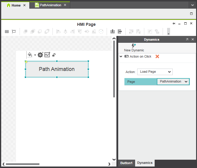
'Action on Click' dynamic with 'Load page' action for 'Path Animation' button
- Open the 'Home' page in the editors area and select the button in the page.
- Select the 'Dynamics' tab in the properties window.
- Left-click the 'New Dynamic' button at the top of the tab and select 'Action > Action on Click'.
- In the 'Action' drop-down list, select the entry 'Load page'. The 'Page' property is added.
- Left-click right of the 'Page' parameter and select the page 'PathAnimation' from the drop-down list.
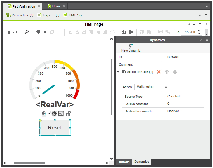
'Action on Click' dynamic with 'Write value' action for 'Reset' button
- Select the 'Reset' button.
- Select the 'Dynamics' tab in the properties window.
- Left-click the 'New dynamic' button at the top of the tab and select 'Action > Action on Click'.
- In the 'Action' drop-down list, select the entry 'Write value'.
- Select the HMI tag 'RealVar' as destination variable and enter the value '0' for the 'Source constant' parameter.
Step 5: Write the project image to the controller
In addition to the application logic and all relevant configuration/parameterization data of the project, the built project image will contain HMI application data.
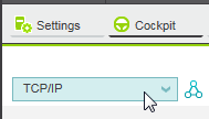
- Open the 'Cockpit' editor of the controller node and select 'TCP/IP' from the drop-down list on the top left.
- In the PLANT, right-click the controller node and select 'Write and Start Project' from the context menu or press <F5> on your keyboard to build the project image, write it to the controller and start execution. Alternatively, click the
 button on the 'Cockpit' toolbar.
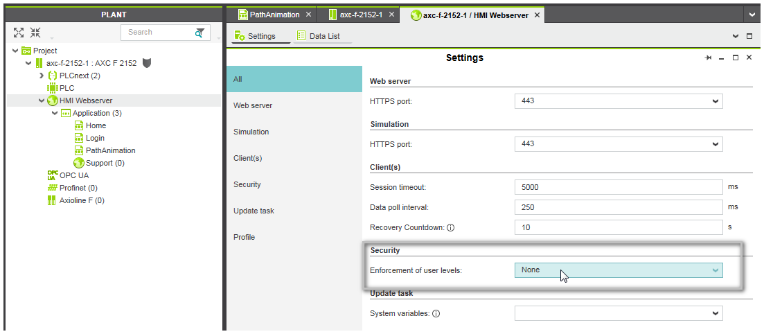
Step 6: Disable enforcement of access rights
By default, security for HMI is enabled, i.e., all HMI pages and objects are not available to users when running the HMI application on the controller. In order to disable security for HMI, the 'Enforcement of user levels' parameter available on the 'HMI Webserver | Settings' editor must be changed from 'PLCnext user management' to 'None'.
- Double-click on the HMI Webserver node in the PLANT.
- In the editors area, open the settings editor.
- In the 'Security' section, change 'Enforcement of user levels' to 'None'.
Step 7: Run the HMI application
- If the 'Cockpit' editor is not already open in the editors areas, double-click the controller node in the PLANT and open the editor.
- Click the
 button on the 'Cockpit' toolbar.The default web browser that is configured for your computer loads the HMI application and starts with the display of the HMI page specified as startup page (in our example, the page 'home' is displayed).Clicking the 'Path Animation' button opens the page showing the radial gauge.