Enabling/Disabling Display of Device Graphics
The devices in the 'Physical Topology' editor and the 'Unconnected Devices' subeditor can be displayed with individual icons (device graphics) or standard icons. You can switch the display by clicking the  button in the toolbar of the 'Physical Topology' editor.
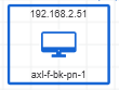
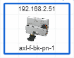
If the devices are displayed with individual icons (toolbar button appears pressed), the device icon stored in the device description file of the device (e.g., FDCML, GSDML, etc.) is shown as device symbol in the editors. The frame color indicates the device status, i.e., whether the device is only an online device, only a project device without assigned online device or an online device with assigned project device. If the FDCML files does not contain a device icon, the device-specific type icon is shown (same icon as used in the PLANT).
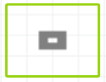
 | Standard icon(Device color and frame color indicate device status) |
 | Individual icon for the topology representation stored in the device description file of the device(Frame color indicates device status.) |
 | Device-specific type icon stored in the device description file. The icon is used if the device description file does not contain an individual icon (see above).(Frame color indicates device status.) |