SF_EDM (External Device Monitoring)
Help version 1.1 / Issue date: 2018.03
The following description is valid for the function block SF_EDM_V2_0z, Version 2.0z (where z = 0 to 9).
|
Short Description
| The safety-related SF_EDM (External Device Monitoring) function block monitors the defined initial state and the switching behavior of contactors connected to the Safety PLC.S_StartReset can be used to specify a start-up inhibit.
Non-conformance to safety function requirements
Ensure that the contactors used correspond to the results of the risk analysis carried out in accordance with ISO 13849-1. |
|
|
Block Icon
| 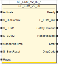 |
|
Inputs
|  Activate Activate
| Short description | Value |
State-controlled input for activating the function block. Data type: BOOL
Initial value: FALSE |
-
FALSE: Function block inactive.
-
TRUE: Function block activated.
|
Refer to the topic "Activate" for details.
S_OutControl
| Short description | Value |
State-controlled input for controlling contactors connected to the S_EDM_Out function block output.Data type: SAFEBOOL
Initial value: SAFEFALSE |
-
SAFEFALSE: Request to switch S_EDM_Out to SAFEFALSE (stop request)
-
SAFETRUE: Request to switch S_EDM_Out to SAFETRUE, taking into account S_EDM1 and S_EDM2.
|
Refer to the topic "S_OutControl" for details.
S_EDM1 and S_EDM2
| Short description | Value |
State-controlled inputs for feedback signals from the connected contactors. Data type: SAFEBOOL
Initial value: SAFEFALSE
Note
If only one feedback signal is used, this must be connected in parallel to both inputs S_EDM1 and S_EDM2. |
Both inputs must show the SAFETRUE state (initial state of the contactors) for the function block to be able to switch the S_EDM_Out output to SAFETRUE. |
-
SAFEFALSE: Connected contactor is picked up (switching state)
-
SAFETRUE: Connected contactor has dropped out (initial state)
|
Refer to the topic "S_EDM1 and S_EDM2" for details.
MonitoringTime
| Short description | Value |
Input for specifying the maximum response time for the switching operations of the connected contactors.Data type: TIME
Initial value: #0msThe switching operations are evaluated via the S_EDM1 and S_EDM2 inputs.
If the specified response time has been exceeded, the Error output is switched to TRUE and the S_EDM_Out output is switched to SAFEFALSE as a result. | Enter a time value according to your risk analysis.Refer to the first warning below this table. |
Non-conformance to safety function requirements
- Verify that the time value set at MonitoringTime corresponds to your risk analysis.
- Be sure that your risk analysis includes an evaluation for incorrectly setting the time value applied to the MonitoringTime input.
- Validate the overall safety-related function with regard to the set MonitoringTime value and thoroughly test the application.
|
Refer to the topic "MonitoringTime" for details.
S_StartReset
| Short description | Value |
State-controlled input for specifying the
start-up inhibit after the Safety PLC has been started up or the function block has been activated.An active
start-up inhibit must be removed manually by means of a positive signal edge at the Reset input. A deactivated
start-up inhibit causes the S_EDM_Out output to switch to SAFETRUE automatically when the function block is activated and the safety-related function is not requested.Data type: SAFEBOOL
Initial value: SAFEFALSE |
-
SAFEFALSE: With
start-up inhibit
-
SAFETRUE: Without
start-up inhibit
|
Non-conformance to safety function requirements
- Be sure that your risk analysis includes an evaluation if the start-up inhibit is deactivated (S_StartReset = SAFETRUE).
- Observe the regulations given by relevant sector standards regarding the start-up inhibit.
- Verify that a suitable start-up inhibit is in place at another location or using other means if the start-up inhibit is deactivated by setting S_StartReset = SAFETRUE.
|
Refer to the topic "S_StartReset" for details.
Reset
| Short description | Value |
Edge-triggered input for the reset signal:
- Resetting error messages when the cause of the error is no longer present.
- Manual resetting of an active start-up/restart inhibit (depending on which type(s) of inhibit the function block provides).
Data type: BOOL
Initial value: FALSE |
-
FALSE: Reset is not requested
- Edge FALSE > TRUE: Reset is requested
|
Note
Resetting does not occur with a negative (falling) edge, as specified by standard EN ISO 13849-1, but with a positive (rising) edge.
To implement the reset with a falling edge (with regard to the mandatory acceptance procedure), use the function block SF_Reset. |
Resetting the function block by means of a positive signal edge at the Reset input can cause the S_EDM_Out output to switch to SAFETRUE immediately (depending on the status of the other inputs).
Unintended start-up
- Include in your risk analysis the impact of the reset by means of a positive signal edge at the Reset input.
- Make certain that appropriate procedures and measures (according to applicable sector standards) have been established to help avoid hazardous situations when resetting.
- Do not enter the zone of operation when resetting.
- Ensure that no other persons can access the zone of operation when resetting.
- Use appropriate safety interlocks where personnel and/or equipment hazards exist.
|
Refer to the topic "Reset" for details.
|
|
Outputs
| Ready
| Short description | Value |
| Output for signaling "Function block activated/not activated".Data type: BOOL |
-
FALSE: Function block is not activated (Activate = FALSE) and all outputs of the function block are switched to FALSE/SAFEFALSE.
-
TRUE: Function block is activated (Activate = TRUE) and the output parameters represent the state of the safety-related function.
|
Refer to the topic "Ready" for details.
S_EDM_Out
| Short description | Value |
| Output for the signal to control the connected contactors.Data type: SAFEBOOL |
-
SAFEFALSE:
- Control signal at input S_OutControl = SAFEFALSE
- or at least one of the connected contactors is not functioning correctly (initial state and/or switching behavior not OK)
- or the function block is not activated
- or the start-up inhibit is active
- or the error message is present.
-
SAFETRUE:
- Control signal at input S_OutControl = SAFETRUE
- and the connected contactors are functioning correctly (initial state and switching behavior OK)
- and the function block is activated
- and the start-up inhibit is not active
- and no error message is present.
|
Refer to the topic "S_EDM_Out" for details.
SafetyDemand
| Short description | Value |
Output for signaling "safety-related function requested".
This output displays whether the safety chain is interrupted and as a result, the attention of the operator is required. Data type: BOOL |
-
FALSE: Safety-related function is not requested.
-
TRUE: The safety-related function is requested.
|
Refer to the topic "SafetyDemand" for details.
ResetRequest
| Short description | Value |
Output for signaling "reset is required".
This output indicates whether a reset by the operator is required. Data type: BOOL |
-
FALSE: No reset required.
-
TRUE: A reset is required:
- to remove an active start-up or restart inhibit (if available for this function block)
-
or to reset an error.
|
Refer to the topic "ResetRequest" for details.
Error
| Short description | Value |
| Output for error message.Data type: BOOL |
-
FALSE: No error is present (that is to say, the FB is not in an error state) or the FB is not active.
-
TRUE: The function block has detected an error. The error state is shown at the DiagCode output.
|
Refer to the topic "Error" for details.
DiagCode
| Short description | Value |
| Output for diagnostic message.Data type: WORD | Diagnostic message of the function block.
The possible values are listed and described in the topic "Diagnostic codes". |
Refer to the topic "DiagCode" for details.
|
| Detailed information | Signal sequence diagram
This diagram is based on a typical interconnection with a start-up inhibit after the function block has been activated or the Safety PLC has started up (S_StartReset = SAFEFALSE).
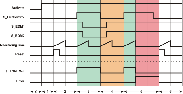
| 0 | The function block is not yet activated (Activate = FALSE). As a result, all outputs are FALSE or SAFEFALSE. |
| 1 | After the function block has been activated by Activate = TRUE, the start-up inhibit is active at first. |
| 2 | When the FALSE > TRUE edge applies at the Reset input, the start-up inhibit is removed and the time set at MonitoringTime for the two inputs S_EDM1 and S_EDM2 is started.
The monitoring time expires without result, as inputs S_EDM1 and S_EDM2 are both SAFETRUE. |
| 3 | The feedback signals at inputs S_EDM1 and S_EDM2 report the initial state of the contactors (S_EDM1 and S_EDM2 are SAFETRUE). In this state, S_OutControl = SAFETRUE. Monitoring time measurement begins at this point and the S_EDM_Out output becomes SAFETRUE.
Both feedback signals S_EDM1 and S_EDM2 switch to SAFEFALSE during the time set at MonitoringTime. Consequently, both monitored contactors function correctly, so that the S_EDM_Out output remains SAFETRUE and the Error output remains FALSE. |
| 4 | The state at the S_OutControl input switches to SAFEFALSE, which results in the S_EDM_Out output switching to SAFEFALSE.
Monitoring time measurement starts again with the state change at S_EDM_Out. Both feedback signals S_EDM1 and S_EDM2 switch to SAFETRUE correctly during the time set at MonitoringTime (initial state of the contactors). As a result, the Error output remains FALSE. |
| 5 | The S_OutControl input becomes SAFETRUE, which switches the S_EDM_Out output to SAFETRUE. At this time, both the feedback signals S_EDM1 and S_EDM2 = SAFETRUE (initial state of the connected contactors).
The timer set at MonitoringTime starts when the S_EDM_Out output switches to SAFETRUE. The feedback signals at inputs S_EDM1 and S_EDM2 do not switch to SAFEFALSE during the monitoring time, as the connected contactors may be inoperable, for example.
After the time set at MonitoringTime has elapsed, output Error = TRUE and output S_EDM_Out = SAFEFALSE. |
| 6 | The error message is reset (Error becomes FALSE) when the positive edge applies at the Reset input. This signal edge also starts the timer set at MonitoringTime. The monitoring time expires without result, as the feedback signals at the inputs S_EDM1 and S_EDM2 are still SAFETRUE. |
Application example
In this example, the safety-related SF_EDM function block monitors the switching behavior of a contactor K1 connected to output terminal 1.1 of the safety-related output device PSDO.
Via input terminal 1.1 of the safety-related input device PSDI 1, an N/C contact provides single-channel feedback signal from the contactor to the S_EDM1 and S_EDM2 inputs (single-channel application up to Cat. 2). The resulting signal of the input terminal is assigned to the global I/O variable K1_Feedback.
The reset button S1 is connected to the input terminal 1.1 of the standard input device DI 1. The signal at input terminal 1.1 assigned to the global I/O variable S1_Reset_EDM is used to remove the start-up inhibit and reset the error states after the cause of the error has been removed.
Note
The S_OutControl input is controlled by another safety-related function block or a safety-related function within the program. |
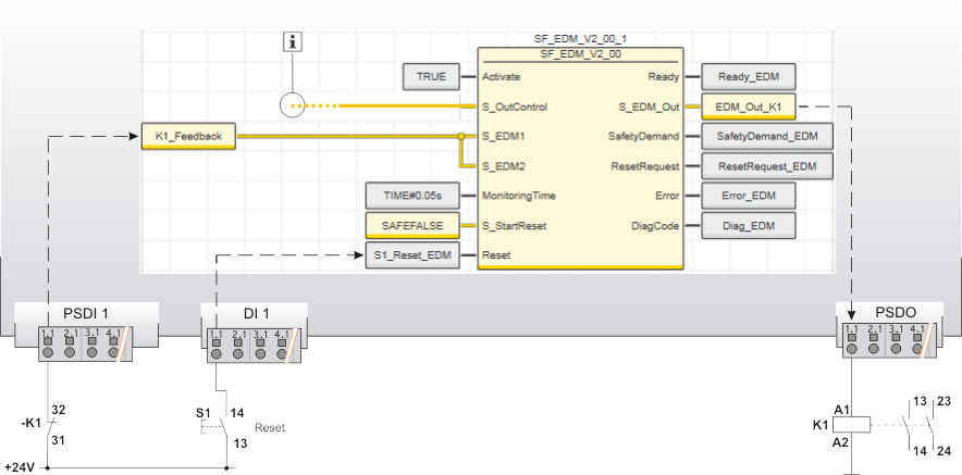
| K1 | Contactor or relay with positively driven contacts. |
| S1 | Reset |
 | See note above the illustration. |
Function block instantiation
The IEC 61131-3 standard defines function block instantiation. Instantiation means, a function block is defined once and can be used (instantiated) several times. This applies to all standard and safety-related FBs (local POUs as well as firmware and user library FBs).
Why instantiation?
A function block has an internal memory where it stores its own processing data (local variables). As a consequence, the output values calculated by the FB depend on the internally stored values. The same input values applied to an FB instance do not necessarily deliver the same results in another FB instance.
Therefore, it is necessary to store the internal data of the FB to a separated memory area each time the function block is processed, i.e., for each FB instance. To uniquely identify each FB instance and to clearly separate its memory area, instance names are used. The instance name of a function block has to be declared in the 'Variables' table of the POU where the FB is going to be used.
The following applies:
- Function blocks can be instantiated in other function blocks or in program POUs. Calling FBs in function POUs is not possible.
- Functions are called without instantiation because they do not have an internal memory.
Safety-related and standard (non-safety-related) code is strictly distinguished in PLCnext Engineer. If a Safety PLC is included in your project, the following applies:
- Safety-related FBs can only be instantiated in safety-related POUs but not in standard (non-safety-related) POUs.
- User-defined standard FBs can only be instantiated in standard POUs. They cannot be called in safety-related POUs.
- Particular standard firmware FBs can be instantiated in both safety-related and standard POUs.
Note
When inserting a standard FB into a safety-related SNOLD network, the rules for implicit type conversion (safety-related to standard) apply. |
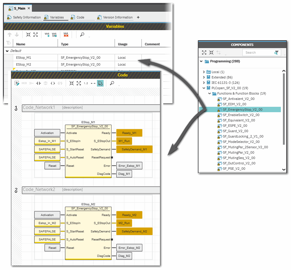
Example for the instantiation of a safety-related PLCopen function block
The safety-related PLCopen function block 'SF_EmergencyStop_V2_00' was inserted into the project via a library. It is then available in the 'Programming' category of the COMPONENTS area. There is a folder with the same name as the library that provides the FBs for insertion into the safety-related code.
The FB is to be called twice in the code of the safety-related program 'S_Main' to evaluate the status of two safety-related emergency stop command devices. For each FB instance, an instance name is declared in the 'Variables' table of the calling program: EStop_M1 and EStop_M2. The FB instances have been inserted into the code worksheet, each instance with different variables connected to its input and output formal parameters.
Additional information is available in the following sections:
|