State machine diagram
The states and hexadecimal codes shown in the diagram are explained in the topic "Diagnostic codes".
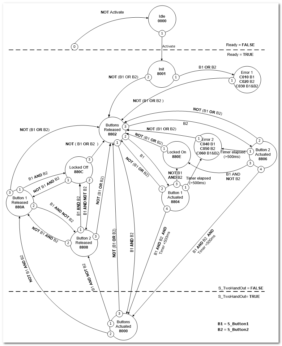
- The state diagram shows three areas: At the top, the FB is not active and in the defined safe state (i.e., safety outputs are SAFEFALSE). In the middle, the FB is active and in the defined safe state. In the bottom area, the FB is in the normal state, i.e., the safety outputs are SAFETRUE.
- The priorities of possible parallel transitions are indicated by numbers (0 = highest priority).
- The transition from any state to the Idle state (due to Activate = FALSE) is not shown in the diagram. However, these transitions always have the priority 0.