Additional application example
This section describes an additional possible application, where the function block evaluates a three-stage enable switch.
The function block must only be used in an actual application once a risk analysis has been conducted.
Details of the risk category/SIL/PL have not been included here, as classification is always based on the application in which the function block is used.
| Hinweis
The use of the function block alone is not sufficient to execute the safety-related function according to the Cat./SIL/PL determined by the risk analysis. In conjunction with the safety-related I/O device used, additional measures must be taken to meet the requirements of the safety-related function. These include, for example, the appropriate wiring and parameterization of the inputs and outputs as well as measures to exclude (design out) errors that cannot be detected. For additional information, please refer to the documentation provided with the safety-related I/O device used. |
| Hinweis
Please refer to the notes in the User Manual on proper electrical connection of the Sicherheitssteuerung and the extension modules (e.g., connecting the three-stage, manually actuated enable switch). |
Evaluating a three-stage enable switch. Confirming the selected operating mode using SF_ModeSelector.
This example describes the evaluation of a three-stage enable switch by the SF_EnableSwitch function block. The enable switch is used to manually confirm an operating mode of a machine. The operating mode is selected by means of a three-stage mode selector switch S1, which is evaluated using the safety-related SF_ModeSelector function block.
In order to operate the controlled machine in operating mode 2 (in the example shown, this is setup mode) or 3 (manual mode), the selected mode must be enabled manually by pressing the enable switch.
Connecting the SF_EnableSwitch function block:
- The function block is perpetually activated by the TRUE constant at the Activate input.
- The enable switch S5 is connected to input terminals 6.1 and 7.1 of the safety-related input device PSDI 1. The signal of input terminal 6.1 is assigned to the global I/O variable S5_SwitchCH1_In, which in turn is connected to the function block input S_EnableSwitchCh1. The signal of input terminal 7.1 is assigned to the global I/O variable S5_SwitchCH2_In, which in turn is connected to the function block input S_EnableSwitchCh2.
- The selected operating mode is confirmed at input S_SafetyActive of the SF_EnableSwitch function block in the form of a feedback signal issued by the speed monitor, see note below.
- A restart inhibit is set via S_AutoReset of the SF_EnableSwitch function block. This inhibit becomes active after a valid signal sequence returns at the function block inputs S_EnableSwitchCh1 and S_EnableSwitchCh2. The Reset button S4 for removing the restart inhibit is connected to input terminal 1.1 of the standard input device DI 1. The reset signal is assigned to the global I/O variable S4_Reset. The reset button resets error states for both function blocks.
Connecting the SF_ModeSelector function block:
- The constant TRUE at the Activate input also causes the safety-related SF_ModeSelector function block to be permanently activated.
- The mode selector switch S1 to be evaluated is connected to the three input terminals 1.1, 2.1 and 3.1 of the safety-related input device PSDI 1. The signals are assigned to the global I/O variables and the function block inputs are connected as follows:
Terminal Global I/O variable Function block input 1.1 S1_State0_In S_Mode0 2.1 S1_State1_In S_Mode1 3.1 S1_State2_In S_Mode2 - A key switch S2 is connected to input terminal 4.1 of the safety-related input device PSDI 1. The signal is assigned to the global I/O variable S2_LockMode_In, which in turn is connected to the S_Unlock input of the SF_ModeSelector function block. Locking the key switch (S_Unlock = SAFEFALSE) locks the operating mode that has been set.
- The AutoSetMode input is switched to FALSE, which means that manual confirmation of the set operating mode is required at the S_SetMode input. A button S3 is connected to the input terminal 5.1 of the safety-related input device PSDI 1 for this purpose. The signal is assigned to the global I/O variable S3_SetMode_In, which in turn is connected to the function block input S_SetMode.
- The signal of reset button S4 connected to input terminal 1.1 of the standard input device DI1 is used for resetting error messages and removing the active restart inhibit (positive signal edge at the Reset function block input). The global I/O variable S4_Reset is assigned to the function blocks SF_EnableSwitch and SF_ModeSelector.
| Hinweis
Notes on the graphic: The S_Mode0Sel to S_Mode2Sel enable signals of the SF_ModeSelector function block have the following functions: (1): Automatic mode. (2): Setup mode. Request for the safely reduced speed at the speed monitor. (3): Manual mode. Connecting the SF_EnableSwitch function block: (4): The S_SafetyActive input of the SF_EnableSwitch function block is connected to the feedback signal of the speed monitor. This feedback signal is used to set the operating mode selected (reduced speed). (5): The S_EnableSwitchOut enable signal of the SF_EnableSwitch function block is connected to additional safety-related function blocks or functions and controls the application accordingly. |
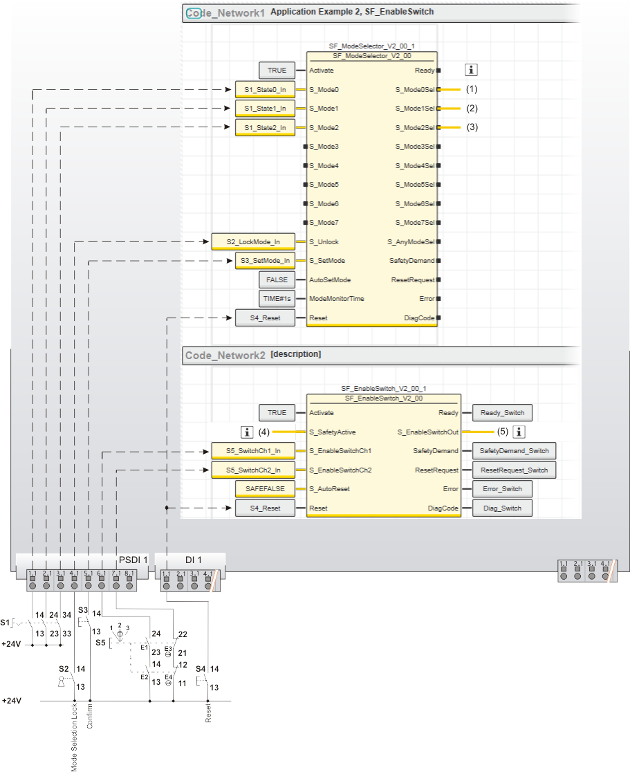
| S1 | Mode selector switch with 3 switch positions |
| S2 | Key switch |
| S3 | Confirmation |
| S4 | Reset |
| S5 | Three-stage enable switch |
 | See note above the illustration. |