- Home
- Funktionen/Funktionsbausteine - Referenz
- Safety FBs in PLCopen_SF_V2_00 Library
- SF_ModeSelector
SF_ModeSelector
Help version 2.0 / Issue date: 2024.03
The following description is valid for the function block SF_ModeSelector_V2_0z, Version 2.0z (where z = 0 to 9).
| Short Description | The safety-related SF_ModeSelector function block evaluates the states of a mode selector switch with up to eight positions.A mechanical mode selector switch can be used to set a specific operating mode (e.g., service mode, setup mode, cleaning mode, etc.). Each operating mode can have a different safety-related function. | ||||||||||||||||||||||||||||||||||||||||
| Block Icon | |||||||||||||||||||||||||||||||||||||||||
| Inputs |  Activate Activate
Refer to the topic "Activate" for details. S_Mode0 to S_Mode7
Refer to the topic "S_Mode0 to S_Mode7" for details. S_Unlock
Refer to the topic "S_Unlock" for details. S_SetMode
Refer to the topic "S_SetMode" for details. AutoSetMode
Refer to the topic "AutoSetMode" for details. ModeMonitorTime
Refer to the topic "ModeMonitorTime" for details. Reset
Refer to the topic "Reset" for details. |
||||||||||||||||||||||||||||||||||||||||
| Outputs | Ready
Refer to the topic "Ready" for details. S_Mode0Sel to S_Mode7Sel
Refer to the topic "S_Mode0Sel to S_Mode7Sel" for details. S_AnyModeSel
Refer to the topic S_AnyModeSel for details. SafetyDemand
Refer to the topic "SafetyDemand" for details. ResetRequest
Refer to the topic "ResetRequest" for details. Error
Refer to the topic "Error" for details. DiagCode
Refer to the topic "DiagCode" for details. |
||||||||||||||||||||||||||||||||||||||||
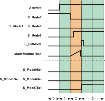
| Detailed information | Signal sequence diagram
The diagram shows the signal sequence for a valid operating mode switchover within the monitoring time set at ModeMonitorTime.
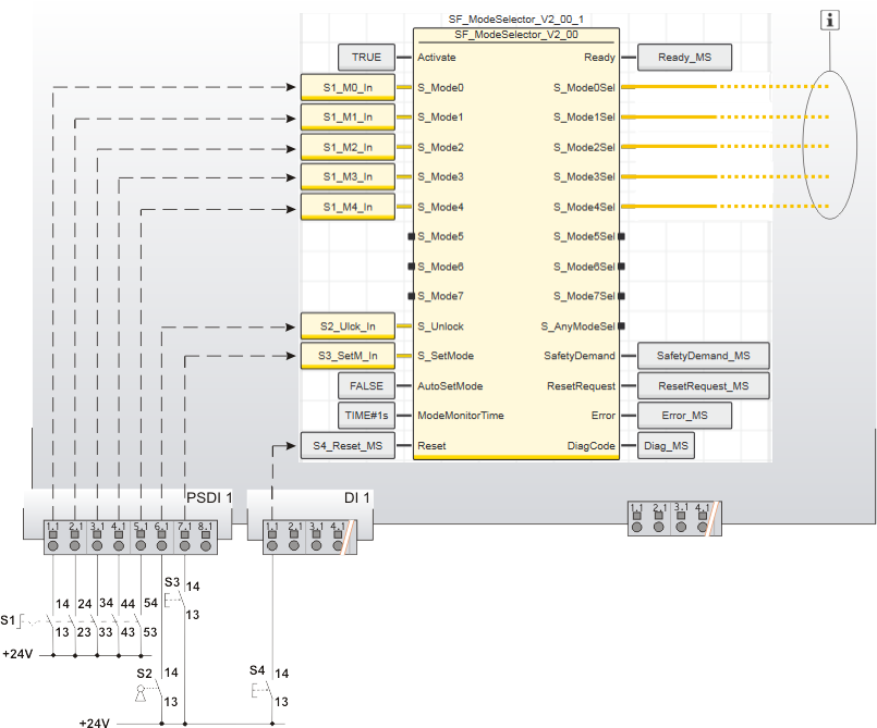
Application example
This example uses a five-stage mode selector switch S1 to show how operating modes are selected. The signals of the five N/O contacts of the mode selector switch are connected to the five input terminals 1.1 to 5.1 of safety-related input device PSDI 1. The signals are assigned to the global I/O variables and the function block inputs are connected as follows:
As a five-stage mode selector switch is evaluated, the function block inputs S_Mode5 to S_Mode7 remain unconnected. A key switch S2 is connected to input terminal 6.1 of the safety-related input device PSDI 1. The input signal is assigned to the global I/O variable S2_Ulck_In, which in turn is connected to the S_Unlock input of the function block. Closing the key switch (S_Unlock = SAFEFALSE) locks the operating mode that has been set. A FALSE constant is connected to the AutoSetMode input, which means that a manual confirmation of the set operating mode is required at the S_SetMode input. Button S3 is connected to input terminal 7.1 of the safety-related input device PSDI 1 for this purpose. Its input signal is assigned to the global I/O variable S3_SetM_In, which in turn is connected to the S_SetMode input of the function block. A reset button S4, which is connected to input terminal 1.1 of the standard input device DI 1 is used for resetting error messages (positive signal edge at the Reset input of the function block). Its signal is assigned to the global I/O variable S4_Reset_MS, which in turn is connected to the Reset input of the function block.
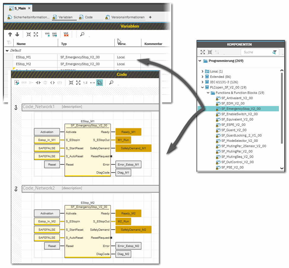
Function block instantiation
The IEC 61131-3 standard defines function block instantiation. Instantiation means, a function block is defined once and can be used (instantiated) several times. This applies to all standard and safety-related FBs (local POUs as well as firmware and user library FBs).
Why instantiation? The following applies:
The safety-related PLCopen function block 'SF_EmergencyStop_V2_00' was inserted into the project via a library. It is then available in the 'Programming' category of the COMPONENTS area. There is a folder with the same name as the library that provides the FBs for insertion into the safety-related code.
|