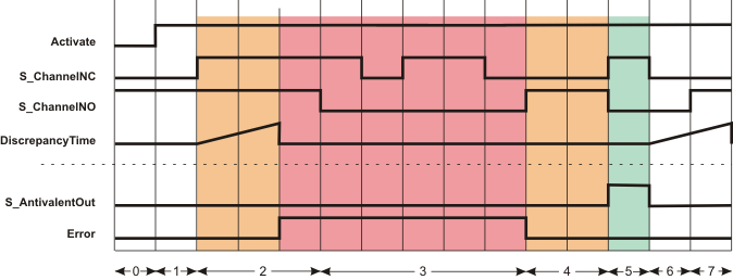
Additional signal sequence diagrams
Temporary intermediate states are not illustrated in the signal sequence diagrams. Only typical input signal combinations are illustrated in these diagrams. Other signal combinations are possible.
The most significant areas within the signal sequence diagrams are highlighted in color.
| Weitere Infos
Please refer also to the diagram found in the overview for this function block. |
Exceeding the discrepancy time
| 0 | The function block is not yet activated (Activate = FALSE). As a result, all outputs are FALSE or SAFEFALSE. |
| 1 | Function block activation (Activate = TRUE). In the meantime, input S_ChannelNC is SAFEFALSE and input S_ChannelNO is SAFETRUE. |
| 2 | S_ChannelNC switches to SAFETRUE. This starts measurement of the discrepancy time. Once the time set at DiscrepancyTime has elapsed, the S_ChannelNC and S_ChannelNO inputs have the same states. This results in an error message (Error output = TRUE). The S_AntivalentOut output remains in the defined safe state (SAFEFALSE). |
| 3 | Irrespective of the states at the S_ChannelNC and S_ChannelNO inputs, the S_AntivalentOut output remains SAFEFALSE for as long as the error message is active (Error = TRUE). The error message must first be "reset" by S_ChannelNC = SAFEFALSE and S_ChannelNO = SAFETRUE. |
| 4 | Error message is "reset" by S_ChannelNC = SAFEFALSE and S_ChannelNO = SAFETRUE. |
| 5 | Output S_AntivalentOut switches to SAFETRUE, as S_ChannelNC = SAFETRUE and S_ChannelNO = SAFEFALSE. |
| 6 | Output S_AntivalentOut switches to SAFEFALSE, as S_ChannelNC switches to SAFEFALSE. The discrepancy time measurement starts when the state at S_ChannelNC switches. |
| 7 | Output S_AntivalentOut remains SAFEFALSE, as S_ChannelNO switches to SAFETRUE within the time set at DiscrepancyTime. |
