Inserting Controller/Devices via Drag & Drop from the COMPONENTS
The 'Network' category in the COMPONENTS area provides devices for modeling the connected network in the PLANT (including devices form included device libraries and device templates created from already configured devices). You can drag these devices from the COMPONENTS area and drop them either:
- on a tree node in the tree structure under the controller node to be used as engineering devices or
- on the 'Project' node to be used as non-engineering devices.
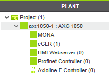
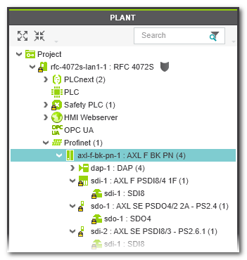
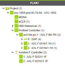
 Example...
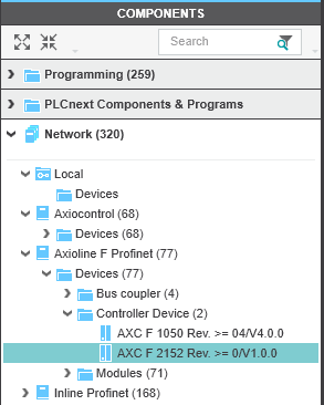

Mouse cursors while dragging
 | PLCnext Engineer only allows dropping of a device on a PLANT node if the device is allowed at this position. In this case, the '+' symbol added to the cursor indicates "insertion possible at this position". |
 | Otherwise, the "forbidden" symbol indicates that the device cannot be inserted. |
Further information
- If the controller device includes a Safety PLC and you are not logged on to the Safety-related Area, you first have to enter the password for accessing the Safety-related Area. If this is the first edit operation of safety-related data in the current project, you are now prompted to define a password. Refer to the topic "Safety-Related Area with Password Protection" for details.
-
Automatic assignment of IP address:
The 'IP range' set for the project influences the insertion of a new controller or device: double-click the 'Project' node, open the 'Settings' editor and select the 'IP subnet' category. A newly inserted controller or
Profinet bus device automatically obtains the next free IP address of the project 'IP range' set here. Therefore, specify the desired IP range according to your requirements prior to inserting devices.
Refer to the topic "Configuring the IP Settings of the Project".