Matlab® Viewers in PLCnext Engineer
The code of a Matlab® model program can be displayed in read-only mode in PLCnext Engineer. The layout in the Matlab® viewers is inspired by the respective Matlab® code layout.
For each of the supported Matlab® code types, a suitable viewer is available:- Simulink® viewer
- Stateflow charts viewer
- Truth Tables viewer
To open a Matlab® program in the respective viewer, double-click the corresponding type in the COMPONENTS area under 'PLCnext Components & Programs'. If submodules/subprograms are contained, you can use the breadcrumb bar to navigate (see below).
To view a model in online mode for debugging purposes, you have to select an instance via the context menu. See topic "Monitoring/Debugging Matlab®
Code" for details.
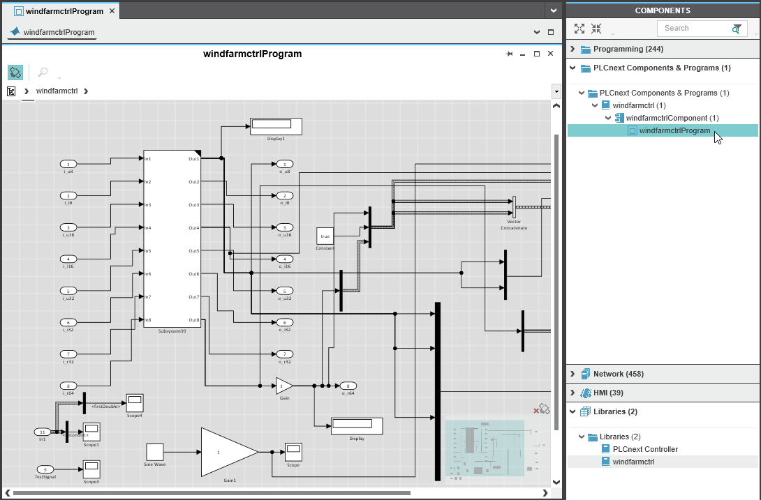
General viewer functions: navigation and overview map
Using the button (1) in the viewer toolbar, you can switch on/off the overview map. This map facilitates the orientation and navigation in the viewer. You can navigate in the worksheet by dragging this area in the map.
Matlab® Simulink® code may contain submodules/subprograms. Using the breadcrumb bar (2) below the toolbar, you can navigate between the module and its subprograms. In our example, the sflow module contains several subprograms (Simulink®, Stateflow charts, Truth Tables, etc.).
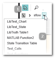
By clicking the icon at the beginning of the breadcrumb line, you can open a selection window for directly accessing submodules/subprograms. The window provides the usual filter function and the contained tree can be expanded ( ) and collapsed (
 ).
).
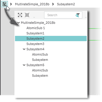
Alternatively, you can double-click the respective block icon in the graphical code to open a subprograms.
Matlab® code can be printed.
Matlab® code and viewer types
Programs and subprograms can be implemented as Simulink® models, State Transition Diagrams (Classic, Mealy, and Moore charts are supported) or Truth Tables. State Transition Diagrams are displayed in the Stateflow viewer.
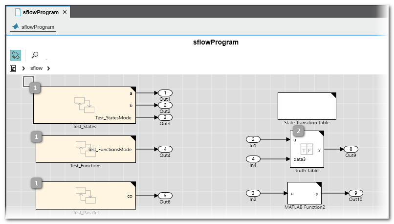
Generally, submodules/subprograms are represented by a block icon with a black triangle in the upper right corner, as shown in the following examples.
 Example: Simulink® viewer with Simulink® submodule
Example: Simulink® with contained Stateflow chart and Truth Table submodules
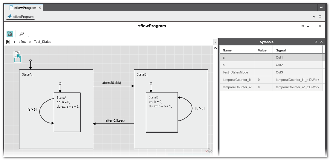
Example: Stateflow chart viewer with Symbol viewer
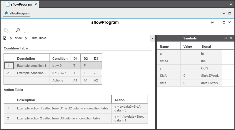
Example: Truth Table viewer with Symbol viewer
Example: State Transition table viewer
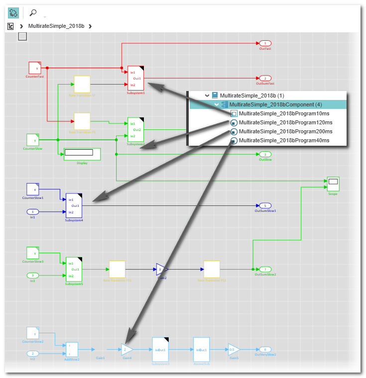
Viewer for multirate programs shows all partial programs
As described in the introduction, a Matlab® program may consist of several partial programs which can be assigned to different tasks in your solution. This way, different update cycles can be used within one model. Refer to the section "Multirate programs consisting of several partial programs" on detailed information and how to integrate them by assigning them to different tasks.
A subprogram does not have an own code view. When opening any of the partial programs in the COMPONENTS area, always the main program is opened which contains all subprograms each represented in a different color.