Matlab® Integration in PLCnext Engineer
This help chapter provides the following information:General information on Matlab® libraries
With PLCnext Technology controllers and PLCnext Engineer, you can integrate Matlab® models.
Such models have to be exported as library (*.pcwlx) in the Matlab® environment and can then be included in your PLCnext Engineer project and executed on the PLCnext Technology controller. This way, the model-based design and versatile simulation possibilities of Matlab® can be used within the PLCnext Technology platform for automation projects, too.
| Note
For exporting a Matlab® model as PLCnext Engineer library, the software add-on for PLCnext Technology controllers by Phoenix Contact is required in Matlab®. |
| Further Info
For detailed information how to install the software add-on and export a Matlab® model for PLCnext Technology controllers in Matlab®, refer to the user manual "Software add-on for the integration and execution of MATLAB® models on Remote Field Controllers and Axioline F controllers". |
Such a PLCnext Engineer model library contains the generated Matlab® program as PLCnext component in C++ code. Additionally, the library contains metadata which enable the code display in PLCnext Engineer using special Matlab® viewers and enables monitoring of the externally created C++ code.
The following Matlab® code types are supported:- Matlab® Simulink® Code
- Matlab® Stateflow Charts
- Matlab® Truth Tables
- Matlab® State Transition Tables
For each code type, a special viewer is available. Refer to the topic "Matlab® Viewers in PLCnext Engineer" for details.
| Note
In the cross references list, named Matlab® objects are also collected. They are shown with their path to the respective submodule/subprogram ('Location' column). |
Multirate programs consisting of several partial programs
A Matlab® program may consist of several partial programs which can be assigned to different tasks in your solution. This way, different update cycles can be used within one model. Such programs are referred to as multirate programs.
A multirate program must have been structured accordingly in Matlab® and the update rates must have been specified there for each partial program. When generating (exporting) the PLCnext Engineer library in Matlab®, these partial programs are made available as separate subnodes (subprograms) which are visible in the COMPONENTS area after including the library. Such types can be identified by the  icon.
icon.
In the code viewer, such subprograms are represented in different colors and the required task cycle is added to the subprogram name. In PLCnext Engineer, you have to create several tasks with the required cycle times and instantiate the subprograms accordingly as described below.
Refer to the section "How to integrate a Matlab® code in your solution" for details.
How to integrate Matlab® code in your PLCnext Engineer solution
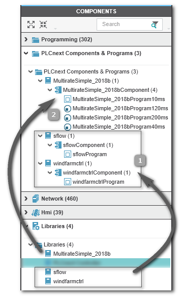
- Add the library in the 'Libraries' category of the COMPONENTS area:
Right-click the 'Libraries' folder, select 'Add User Library...' from the context menu and browse for the library file.The programs contained in the library are then available in the COMPONENTS category 'PLCnext Components & Programs'. Here, a folder has been inserted with all programs contained in the library. Simulink® programs, Stateflow charts and Truth Table models have an identical icon:
If, however, a multirate program (with subprograms) is contained in the library, the individual subprograms are shown separately each with the icon. Both scenarios are shown in the example below.
- Instantiate the external Matlab® program as follows:
- Double-click the 'PLCnext' node in the PLANT and open the 'Tasks and Events' editor.
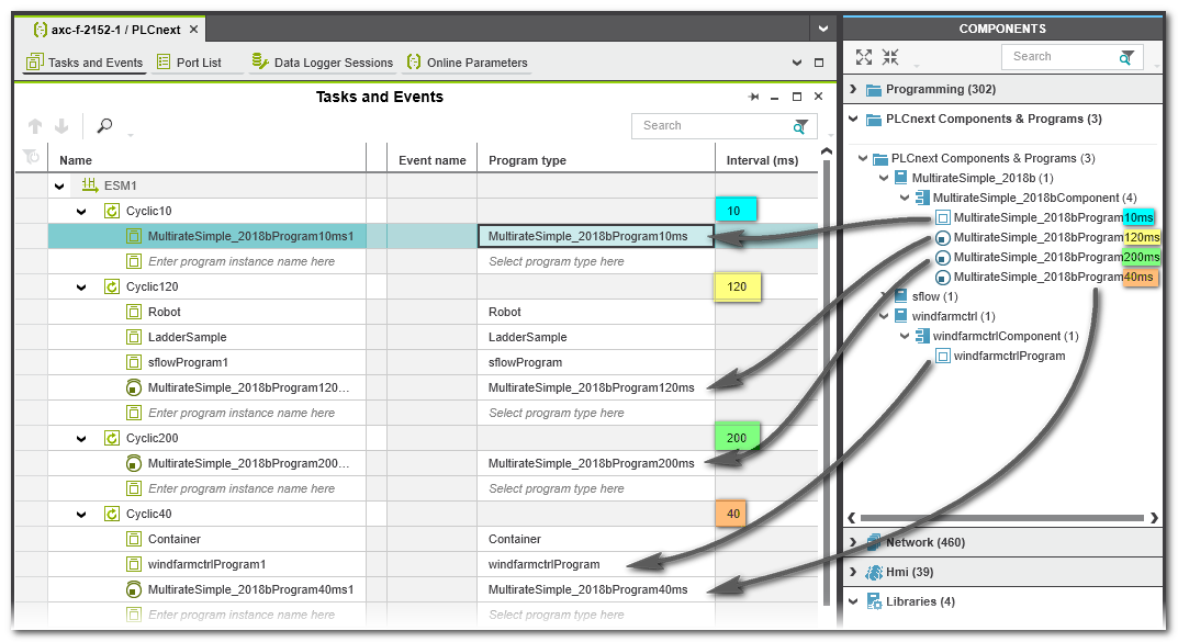
- In the 'Tasks and Events' table, specify a new task, if required. In case of a multicore controller, note that tasks have to be defined under the respective core (ESM node).When instantiating Matlab® multirate subprograms, set the cycle time of each task according to the name of the subprogram to be assigned. For the multirate program in the example above, you would create four cyclic tasks and set the interval to 10 ms, 120 ms, 200 ms, and 40 ms. This instantiation is shown in the example below.
- In the task table, left-click into the 'Program Type' field, which is showing the text 'Select program type here' or move the table cursor using the arrow keys or <Tab>/<Shift>+<Tab> to this table field and press <Enter>. In the Role Picker, select a folder in the tree on the left and then the program on the right by clicking it or pressing the <Enter> key. By selecting and thus inserting the program, a program instance is created. You can edit the default instance name, if desired.When instantiating Matlab® multirate subprograms, make sure that the instance is created in the task with the correct cycle time. PLCnext Engineer checks your task configuration accordingly and verifies that the set task interval corresponds to the recommended update rate set in the Matlab® code (mentioned in the subprogram name). Such subprogram instances get the icon
 in the task table.
A warning message informs you about a wrongly set cycle time. Example: Instantiating several subprograms of a Matlab® multirate program
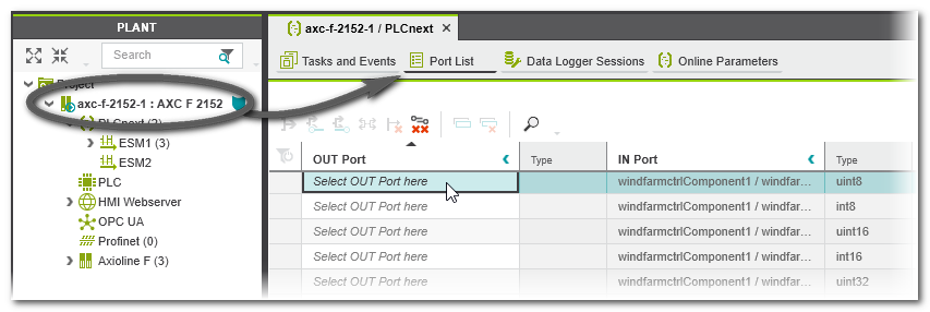
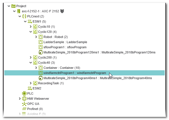
- Open the Port List editor of the 'PLCnext' node. This list shows the ports available in the project. Here, also the ports of the newly instantiated external program are provided (except model-internal testpoints) and can be mapped to other ports of IEC 61131-3-compliant programs or non-IEC 61131-3 programs.You can also open the Port list of the program instance. For that purpose, expand the respective ESM node and task node in the PLANT and double-click the instantiated model. The handling of the Role Picker for mapping IN and OUT ports is described in the topic "Port Lists".
- Map inputs of the Matlab® model to OUT ports available in your PLCnext Engineer application.
- Map outputs of the Matlab® model to IN ports available in your PLCnext Engineer application.