Scanning the Network and Adding Devices/Connections to the Project
This topic contains the following sections:
Using the scan function provided by the 'Physical Topology' editor you can run a single scan or cyclic scan to find all Ethernet devices (hereafter referred to as devices) connected to your network. Based on definable scan options, all reachable devices that respond are visualized in the 'Physical Topology' editor with their provided device values such as the IP address, subnet mask,
system name, etc.
When scanning the network using the set scan options, PLCnext Engineer compares different values such as the IP address, the subnet mask, etc. of the project devices (devices that are contained in the PLANT) to the values of the online devices.
Based on the comparison result, the following applies:
- Devices for which an equivalent device exists in the PLANT, i.e., the IP address of the discovered device and project device are identical, are shown with a black symbol.
- Devices that are not yet contained in the project are shown with a blue symbol. You can add these devices to the project as non-engineering devices via the editor if the corresponding device type is available in the COMPONENTS area (see below for further information).
Scanning the network
To scan the network, proceed as follows:
For the following steps, we assume that you have connected your computer running PLCnext Engineer to the network that is to be scanned for devices.
- Double-click the 'Project' node in the PLANT and open the 'Settings' editor in the editors area.
- In the categories 'SNMP', 'Scan sources', 'Scan details', and 'Network load' on the left, set the scan options used for the network scan. The 'Scan sources' category is the main category providing different scan options that must be set before starting the scan process. All other categories provide optional scan options that you can configure to consider special features.In the 'Scan sources' category, enable and configure the following scan options:
Note
The scan options are not mutually exclusive. It is possible to enable individual or multiple scan options simultaneously. To enable a scan option, activate the corresponding 'Enabled' checkbox. |
 DCP scan
If the 'Enabled' checkbox is activated, the DCP protocol (Discovery and Configuration Protocol) is used to scan for network devices. When scanning, all devices that support DCP will respond to the DCP request and send the requested information back.
From the 'Network adapter' list box, select the network adapter used for the DCP communication. The selection list contains all network adapters that are available in your PC. Network adapters that are currently not connected to the network are visualized by a red cross attached to the symbol in the selection list.
The selection of the network adapter is mandatory.
Ping scan
If the 'Enabled' checkbox is activated, devices are searched using ping scanning. The ping command checks whether devices with an IP address in the defined IP address ranges are reachable in the network.
| Parameter | Description |
| 'Timeout (ms)' | The ping timeout specifies the time in milliseconds after which PLCnext Engineer considers the device as unreachable, i.e., how long the tool waits until a reply from the device.
Value range: 1 to 5,000 ms |
| IP ranges | The address range table contains the IP address ranges that are used for a ping scan. For the ping scan at least one address range must be defined.To define an IP address range, enter the start and end IP address in the table and activate the address range for the network scan by checking the 'Enabled' checkbox'. A new empty address range row is automatically inserted into the table when an address range is confirmed.To delete a configured address range, right-click the row in the table and select 'Delete' from the context menu or press <Del> for a selected row.
Note
The start IP address must be less than the end IP address. |
To exclude specific IP address ranges within the specified ranges from the scan, use the 'Excluded IP ranges' table as described below. |
| Excluded IP ranges | Here you can exclude specific IP address ranges within the specified 'IP ranges' from the scan. For example, if you have a large IP address range configured, you can block individual ranges of addresses that will not be included in the scan.Entering and deleting values in the table are done in the same way as for the 'IP ranges' table (see above). |
SNMP scan
If the 'Enabled' checkbox is activated, devices are searched using Simple Network Management Protocol (SNMP) scanning. When scanning the network, PLCnext Engineer sends an SNMP Broadcast Get Request message to the network. All devices that support SNMP service and respond to this broadcast will be discovered.
| Parameter | Description |
| 'Timeout (ms)' | Set the timeout value in milliseconds while discovering the network devices using SNMP. The timeout specifies the time how long PLCnext Engineer waits for the response of the network device. If the response takes longer than the set time, the SNMP request is aborted. |
| 'Network adapter' | From the 'Network adapter' list box, select the IP configuration of the network adapter used for the SNMP communication. The selection list contains all IP configurations of the network adapters that are available in your PC. The entries consist of the IP address configured for the network adapter and the name of the network connection as it appears in the Network Connections Control Panel program. Network adapters that are currently not connected to the network are visualized by a red cross attached to the symbol in the selection list.The selection of the network adapter is mandatory. |
VRRP scan
If the 'Enabled' checkbox is activated, the network is scanned for virtual routers by analyzing the VRRP (Virtual Router Redundancy Protocol) configuration of the network devices.
With VRRP, two or more physical routers form a VRRP group. The virtual address of the VRRP group is used for communication in the network. In a VRRP group, one router is the master router. All other routers in the VRRP group are backup routers. The master router handles all routing tasks. If the master router fails, a backup router takes over the master router role.
During the network scan, the VRRP configuration of the network device is checked. If the physical address of the device lies within the IP address range specified in the 'IP ranges' table under the 'Ping scan' group, it is checked whether there is a virtual router. If so, the virtual router is shown in the 'Physical Topology' editor in addition to the physical router. (If only the address of the virtual router lies within the specified IP address range, the device is shown as simple Ethernet device.)
Further Info
For details how to enable VRRP for a network device and how to configure the VRRP settings, see the device manual. |
SCB WLAN client scan
If the 'Enabled' checkbox is activated, the network is scanned for WLAN clients that are operated in SCB (Single Client Bridge) mode via SNMP.
In SCB mode, only one Ethernet device may be connected to the WLAN client. The WLAN client adopts the IP address from the Ethernet device behind the client. This means when scanning the network, the Ethernet device will be discovered but not the WLAN client. To find the WLAN client that has the same IP address as the Ethernet device behind the client, configure the 'SCB port' of the WLAN client to which the Ethernet device is connected. In this case, PLCnext Engineer tries to reach the discovered Ethernet device via the selected port. If the Ethernet device is reachable via the port, a second device with the same IP address (in this case the WLAN client) will be shown in the 'Physical Topology' editor.
Discover additional neighbors with LLDP
If the 'Enabled' checkbox is activated, the network is scanned for neighboring devices (devices directly connected to a device) by analyzing the LLDP (Link Layer Discovery Protocol) information of the discovered network device via SNMP.
LLDP is a neighbor-discovery protocol that allows a network device to advertise information about itself to neighboring devices on the local network (LAN). Each network device for which LLDP is enabled sends and receives LLDP messages. The LLDP information is stored in the Management Information Base (MIB) of the network device.
The LLDP setting has no influence on whether the network connections are also examined with the LLDP protocol.
- If desired, adjust further optional scan options in the other categories of the 'Settings' editor.
Further Info
For a description of the scan categories available in the 'Settings' editor, see the topic "Scan Options". |
- In the editors area, open the 'Physical Topology' editor.
Click the  button on the toolbar to start a single scan. To start a cyclic scan with the set scan options, turn the cyclic scan mode on by pressing the
  button on the toolbar. (To stop the cyclic scan mode, press the button again.)
Note
A single scan can be stopped by clicking the  button on the toolbar (button is only active while scanning is in progress). To stop the cyclic scan mode, press the button again. button on the toolbar (button is only active while scanning is in progress). To stop the cyclic scan mode, press the button again. |
The network is scanned according to the set scan options. After completion of a scan, the devices discovered in the connected network are displayed in the 'Physical Topology' editor.
Adding devices and connections to the project
Devices and their connections that were discovered on the network using the scan function of the 'Physical Topology' editor can be added to the project as non-engineering devices (see the following description for the differentiation between engineering and non-engineering devices). Prerequisite for adding the devices is that
- the corresponding device type is available in the COMPONENTS area. This means, a matching type definition of the discovered device is available in the COMPONENTS area.
- the discovered device is not yet contained in the engineering project.
Differentiation between engineering and non-engineering devices
PLCnext Engineer differentiates between the following two types of devices:
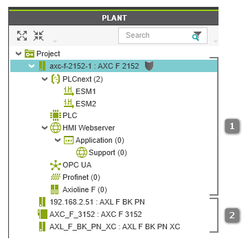
- Engineering devicesEngineering devices are devices that are part of the active controller/Profinet configuration. The active controller/Profinet configuration is represented as hierarchical tree structure in the PLANT where the engineering controller is the root node of the tree and the Profinet node is a child node (see [1] in the figure below). All physical and logical components (hardware and software) of the plant/machine to be controlled are child nodes in the hierarchy.Only the devices in the active configuration are relevant for the engineering project (contains all data such as network and communication settings, device parameterizations, controller runtime configuration, etc. required for the application).
- Non-engineering Ethernet devicesNon-engineering Ethernet devices are devices that are not part of the active controller/Profinet configuration. They are not relevant for the engineering project (see above). Non-engineering devices are shown as single child nodes of the 'Project' node without any sub-structure (see [2] in the figure below). A non-engineering device has only one 'Settings' editor that provides general and Ethernet-specific properties.
Note
Safety-related non-engineering devices do not create any safety-related data (such as parameters) in the project. Therefore, it is not necessary to logon to the Safety-related Area when adding such a device. |
Note
PLCnext Engineer allows to make a non-engineering device as engineering device. This means, the non-engineering device can be added to the engineering project (active controller/Profinet configuration). For details on this procedure, see the topic "Engineering and Non-engineering Devices". |
To add discovered devices as non-engineering devices and connections to the project, proceed as follows:
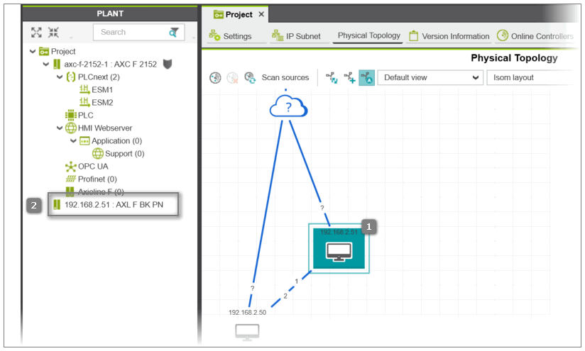
- Select the device(s) and connection(s) in the topology (see [1] in the following figure). (Multi-selection is done in a standard way by Shift-clicking or Ctrl-clicking the elements.) To select all objects in the view, press <Ctrl> + <A>.
- Click the
 button on the editor's toolbar.If a scanned device cannot be uniquely identified because, for example, more than one matching device type is available in the COMPONENTS area, the 'Station structure preview' dialog appears. In the dialog, select the 'Type' of the scanned device from the drop-down list and confirm to continue.The device(s) that are not yet contained in the project are added as non-engineering devices (child nodes of the 'Project' node without any sub-structure) to the project where the device's IP address and type is used as node name (see [2] in the following figure). The added devices and connections are now represented by black symbols in the topology.