- Home
- Coming from PC WORX 6.x
Coming from PC WORX 6.x
This help chapter lists some essential differences between the PC WORX 6.x suite and PLCnext Engineer. It is therefore recommended to lateral entrants for a first orientation.
 Controllers of the PLCnext Technology generation supported
Refer to the topic "PLCnext Technology Controller Generation" for details.
Security-related features implemented in PLCnext Engineer and PLCnext Technology controllers
- Secure devices: role-based security concept with PLCnext Technology controllers.
- Certificates ensure secure communication connections between PLCnext Technology controllers and PLCnext Engineer as well as between the integrated OPC UA server and its clients.
- Signed libraries enable the detection of tampered or modified libraries. See topic "Tamper Protection of Libraries".
- Know-how protected libraries.
- Protection of safety data integrity/consistency.
- Protection of integrity and authorship of safety-related, loadable C functions.
Refer to the topic "Security in PLCnext Engineer" for details.
With PC WORX 6.x and SafetyProg, the development and commissioning of standard (non-safety-related) application and the safety-related application as well as the controlling of the standard controller and the Safety PLC have been performed in different tools. Especially with regard to the communication between the standard controller and the Safety PLC realized by means of exchange variables, this separation results in higher efforts.
PLCnext Engineer, in contrast, supports the complete implementation of a safety-related application if a Safety PLC is included in your project. This includes the adding of safety-related devices to the PLANT, safety-related device parameterization, programming of safety-related code including the mapping of safety-related I/Os.
In the project, the standard (non-safety-related) controller and the Safety PLC are strictly separated. Each of it executes its own application, has its own global variables, and its own runtime configuration. Therefore, the Safety PLC is represented by its own icon in the PLANT. Double-clicking this icon opens the safety-related editors.
The safety-related project data (device structure, code, and device parameterization) as well as the configuration and operation mode of the safety-related controller are protected by two separate passwords. For editing safety-related parts of the project, you have to logon to the Safety-related Area. This is an area of responsibility restricted to authorized members. For writing data to the safety-related controller or changing its operation mode, you have to log on to the controller by entering the Safety PLC password.
Safety-related code and data processed in and generated by PLCnext Engineer is based on the IEC 61131-3 standard and meets the safety requirements defined in the standards IEC 61508, EN IEC 13849 and EN 62061 (depending on the language profile set in the project).
| Further Info
Observe the descriptions in chapter "Safety-Related Application/Area". |
While editing safety-related data (SNOLD code worksheets, variables, the Safety PLC Data List, configuration of the Safety PLC runtime, safety-related device parameters, etc.), the respective editor performs a continuous verification of the worksheet data consistency: the data stored in the data keeping is compared to the data shown in the editor thus preventing unintentional and unrecognized data modifications.
After each editing operation, verified correct data is sealed by calculating a checksum over it and writing the checksum into an inventory file (which is in turn protected by a seal).
Any detected inconsistency (i.e., possible data corruptions) results in an editor error and a safety violation notification.
In PC WORX 6.x, it was necessary to define the programming language acc. to IEC 61131-3 when creating the POU. In PLCnext Engineer, multi-language POUs are possible. This means, that code worksheets in different IEC 61131-3 programming languages can be added in one POU.
Furthermore, PLCnext Engineer provides mixed FBD/LD code worksheets where programming elements from both graphical IEC 61131-3 programming languages can be used.
SNOLD for programming safety-related code
Safety-related code is programmed in SNOLD (Safety Network Oriented Ladder) code worksheets using the safety-related network-oriented graphic editor. Basically, the SNOLD editor works like the NOLD editor and provides additional safety-related features. Refer to the topic "Programming FBD/LD, NOLD and SNOLD", section "Similarities and Differences".
Cockpit instead of PLC control dialog (separate for standard controller and Safety PLC)
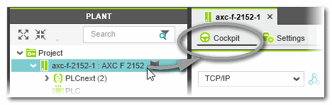
In PC WORX 6.x, PLC-relating commands, such as writing the project, starting, stopping the PLC, etc., were located in the resource control dialog. In PLCnext Engineer, these operations are done in the 'Cockpit' editor.
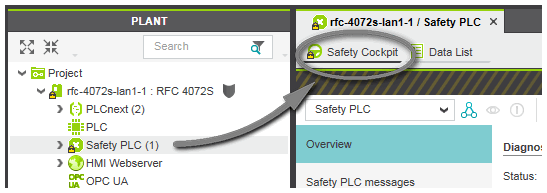
If a Safety PLC is included in your project, it has to be controlled completely independent of the standard (non-safety-related) controller. For that purpose an own 'Safety Cockpit' is provided.
Open the 'Cockpit' as follows:
- Double-click the controller in the PLANT to open its properties in the editors area.
- In the editors area, open the 'Cockpit' editor.
Open the 'Safety Cockpit' as follows:
- Double-click the Safety PLC in the PLANT to open its properties in the editors area.
- In the editors area, open the 'Safety Cockpit' editor.
Refer to the topics "Controlling the Safety Application from the Safety Cockpit ![]() ‣ Cockpit: Controlling the Application
‣ Cockpit: Controlling the Application
×‣ Controlling the Safety Application from the Safety Cockpit
×" for detailed information.
COMPONENTS area instead of project tree (for POU management)
Each POU is considered as type, which is to be instantiated in the project as follows:
- Program POUs have to be instantiated in the controller runtime configuration. Double-click the 'PLCnext' node in the PLANT for that purpose. In the editors area, open the 'Tasks and Events' editor and assign programs to a task.
- Function block POUs have to be instantiated in variables tables of the calling POU (declaration of an instance name) and then called in a code worksheet using a conventional FB call.
COMPONENTS area with types instead of Edit Wizard
In PC WORX 6.x, function and function block POUs are provided in the Edit Wizard for insertion into the code. In PLCnext Engineer, POUs are provided in the category 'Programming' of the COMPONENTS area. From here, they can be dragged into the code or inserted using Intellisense ![]() ‣ Intellisense in the Text Editor
‣ Intellisense in the Text Editor
×‣ Intellisense in the Graphic Editor
× (by simply start typing in the code).
The 'Local' folder contains user-defined POUs, other folders provide standard and firmware POUs.
'PLCnext'/'IEC 61131-3'/'Safety PLC' node in PLANT instead of Instance tree
- as 'PLCnext' node respectively for controllers of the PLCnext Technology generation
- and as 'Safety PLC' node if a safety-related controller is included in the project.
Tasks, events and program instances are to be edited as properties of the respective node.
The standard controller and the Safety PLC are strictly separated. Therefore, the Safety PLC provides its own safety-related runtime configuration.
In programming mode, double-clicking a program/FB instance under a task node opens only the Data List of the corresponding instance. Code worksheets and variables tables of the POUs cannot be opened from the PLANT tree and must be opened via the COMPONENTS area.
In online mode (if PLCnext Engineer is attached to the running application process and a controller status is shown in the PLANT controller icon), double-clicking an instance node opens the online code for the corresponding instance. (Alternatively, you can open online worksheets via the 'Go To Instance Editor' context menu command in code worksheets.)
| Note
Instances of non-IEC 61131-3 programs (from an included PLCnext Technology components library) are also listed under the 'PLCnext' node. |
PLC/Safety PLC runtime Data List instead of resource-global variables worksheet
Resource-global IEC 61131-3 variables (IEC declaration keyword VAR_GLOBAL) are now declared using the 'Global' keyword in the Data List of the controller runtime (which corresponds to the resource configuration element acc. to the IEC 61131-3 standard).
If a Safety PLC is included in your project, standard (non-safety-related) and safety-related data are strictly distinguished. Therefore, resource-global variables of the Safety PLC are declared separately in the Data List of the 'Safety PLC' node. Here, safety-related as well as standard Globals used in safety-related POUs are defined. Furthermore, (safety-related) I/O variables and exchange variables can be declared (see next item).
The requirement to additionally declare each global variable as External variable in the POU where it is used, has not been modified in PLCnext Engineer.
Data assignment (role mapping) instead of entering physical address locations
In PC WORX 6.x, a physical address location has to be entered in the global variables worksheet of the resource (e.g., %Q0.2). By specifying an IO configuration, where address ranges are specified for I/O modules, PC WORX 6.x maps the address locations of global variables to a physical terminal.
In PLCnext Engineer, address mapping is much easier by a simple assignment in the Data List editor. Defining an I/O configuration is no longer necessary. The address assignment in a Data List is called role mapping.
This role mapping does not only simplify the declaration of I/O variables. It also simplifies the creation of exchange variables for the communication between the standard controller and the Safety PLC (if included in your project). Instead of a complicated declaration and assignment process in several tools, exchange variables can now be simply created by mapping variables of the standard controller and to standard variables of the Safety PLC.
The principle of data item assignment (role mapping) in PLCnext Engineer:
In IEC 61131-3 programming, the various engineering disciplines provide different data items that are read and/or written in the application.
- Networking: Process data items (I/O terminals) provided by the controller and I/O modules.
- Programming: Global IEC 61131-3 variables in the IEC 61131-3 application program (user-defined variables as well as pre-defined system variables provided by the runtime).If a Safety PLC is included in your project, standard (non-safety-related) and safety-related data are strictly distinguished. Therefore, resource-global variables of the Safety PLC and the standard controller are declared separately in the 'Data List' of the 'Safety PLC' node and the 'IEC 61131-3' node.
- HMI: HMI tags, used to animate HMI objects on designed HMI pages (depending on variable values) or to control the application via the elements on HMI pages.
By defining assignments between these data items, the various engineering disciplines are mapped and can interact. Assigning these data items means linking the "physical world" (devices) to the "virtual world" (application code and HMI display or device terminal).
PLCnext Engineer allows the simple and comprehensive mapping of data items. For this purpose, a tabular 'Data List' editor is available in PLCnext Engineer.
Examples:- By assigning a global IEC 61131-3 variable to an output process data item (device output terminal), writing this global variable means writing to the assigned output. This is possible for global variables of the standard (non-safety-related) controller and the Safety PLC.
- By assigning a global IEC 61131-3 variable of the standard controller to a global standard variable of the Safety PLC, an exchange variable is created. Exchange variables enable the communication between Safety PLC and standard controller.
- By assigning a global IEC 61131-3 variable of the standard controller to a safety-related input or output variable of the Safety PLC, the standard application can read the value of safety-related inputs and outputs. Writing to such a variable in the standard application is not possible.
- By assigning a global IEC 61131-3 variable to an HMI tag which is in turn mapped to a dynamic property of an HMI object, the value of the IEC variable can be visualized in the HMI application, or it can be written by the HMI object. (This depends on the access type of dynamic property.)Currently, no direct assignments to HMI tags are possible in the Data List of the Safety PLC. However, after assigning a standard variable of the Safety PLC to a global variable of the controller (thus creating an exchange variable), an HMI tag can be created.
- By mapping an IEC 61131-3 variable to an output process data item and to an HMI tag, the application can be controlled via the HMI.
- Only possible with PLCnext Technology controllers: by mapping IN ports and OUT ports of program POUs, communication between programs is even possible between IEC 61131-3-compliant programs and non-IEC 61131-3 programs (developed, for example, in C++).
Note
The 'PLCnext' node of PLCnext Technology targets provides a Port List instead of the Data List.
New Event types for runtime exceptions
In PC WORX 6.x, runtime exceptions such as Division by Zero or Stack Overflow or Array index out of range, were handled by error messages loaded from the runtime into a message dialog and into the message window.
In PLCnext Engineer, new event types are available handling these exceptions (only for non-safety-related controllers):
- Array bounds exceeded
- Stack overflow
- Division by zero
Refer to topic "Task/Event Properties and Types (non-safety-related Controllers only)".
Methods: Object-oriented programming in function blocks
PLCnext Engineer supports object-oriented function blocks: According to IEC 61131-3, 3rd edition, methods can be created in user-defined function block POUs.
Methods can be called internally as well as externally in all supported programming languages.
Refer to topic "Methods".
Import of POU types and data types from PC WORX 6.x projects via PLCopen XML file
PC WORX 6.x provides the possibility to export a project as PLCopen XML file.
PLCnext Engineer supports the import of POUs (program, function blocks and functions) and data types from a PLCopen-compliant XML file (schema version 1.01 or newer). The imported types are added to the respective category in the COMPONENTS area.
Refer to topic "Importing Types (POUs, Data Types)".
Declaration and use of instance-related variables simplified
PLCnext Engineer supports instance related I/O variables according to the IEC 61131-3 standard.
The use of instance-related variables is simplified compared to PC WORX 6.x (where these variables are declared with VAR_GLOBAL_PG and VAR_GLOBAL_FB): after having selected a data direction ('I/Q') in the declaration of a variable in an FB ('Usage = Instance'), one instance-related variable is automatically inserted into the Data List of the controller for each corresponding function block instance. In the Data List, the declaration keyword 'Instance' is used.
Instance-related variables are also possible for program-global variables. For that purpose, a data direction ('I/Q') must be selected for the program-global variable that is declared in a program POU with 'Usage = Program'. In the Data List of the 'IEC 61131-3' node, such instance-related variables get the 'Program' declaration keyword.
Refer to the topic "Instance-related located Variables: 'Instance' and 'Program'".
Program-global variables supported
PLCnext Engineer supports program-global variables. A program-global variable can be used in the program POU where it is declared and in all FB POUs that are instantiated in this program. For that purpose, the program-global variable has to be declared in the local variables table of the FB POU with 'Usage = External'. Refer to the topic "Variable properties and declaration keywords" for details.
By selecting a data direction ('I/Q') for a program-global variable, instance-related variables are automatically created with the keyword 'Program' in the Data List of the resource ('IEC 61131-3' node). In the Data List, the variable is automatically inserted once per each declared instance of this program. Refer to the topic "Instance-related I/O variables: 'Instance' and 'Program'" for further details.
| Note
Program-global variables are not supported for safety-related POUs. |
Easy navigation in the user interface via keyboard
Navigation in PLCnext Engineer is possible with the keyboard anywhere in the user interface:
- Press and hold the keyboard shortcut <Ctrl> + <Tab>.A navigation control appears showing the controls on the left side and the currently open editors on the right:
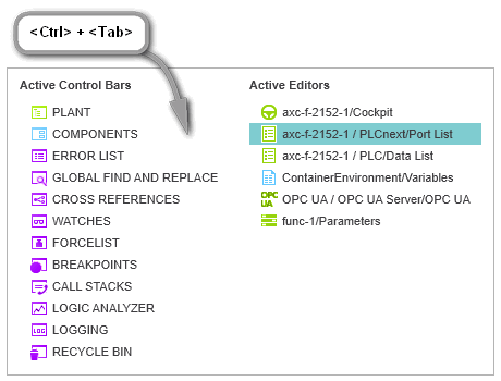
- While holding <Ctrl> + <Tab> down, use the arrow keys on your keyboard to navigate to the desired control or editor and release the shortcut to set the cursor into it.
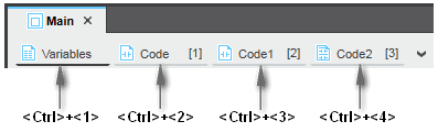
To navigate between the editors of an editor group (represented as tabs at the upper border of the editors area) via the keyboard, you can press the <Ctrl> key combined with the consecutive number of the editor tab, starting with 1.
Example: In the following editor group, the shortcut <Ctrl>+<3> opens the worksheet 'Code1'.
Note that the number in brackets [...] is the number in the execution order of the code worksheets but not the worksheet number.
SFC function blocks with formal parameters for operating modes
PLCnext Engineer extends the IEC 61131-3 standard by implementing SFC operating modes used to control the execution of the SFC code. For that purpose, each SFC function block gets formal parameters by default when it is inserted into a code worksheet.
Refer to topic "SFC Operating Modes and Formal Parameters".
SFC: extended debugging functions
When debugging SFC code worksheets, the graphical editor provides additional debugging commands used to control the SFC step chain execution, to switch the SFC operating mode, reset the step chain, etc.
Refer to topic "Debugging SFC Code".
Powerflow display now implemented as Execution Value mode
The Powerflow mode known from PC WORX 6.x is now available as Execution Value mode. The PC WORX 6.x powerflow signs in the text editor and graphic editor, which indicate whether or not a program part is currently processed, are now available as execution indication signs left to the online values. In the graphic editor, currently processed FU/FB blocks are surrounded by a black rectangle.
PLCnext Engineer provides extended debugging features which allow the debugging of user-defined function POUs and/or the display of execution values in online worksheets (instead of "normal" online values). The PC WORX 6.x powerflow signs are now available as execution indication signs left to the online values.
PLCnext Engineer supports the translation of comments and HMI texts into other national languages. A HMI client is able to switch the HMI language during execution of the application.
See topic "Project Language Translation (Localization)" for details.
PLCnext simulation emulates controller CPU
The controller simulation is a separate application which actually emulates the CPU of the controller set as target your project.
In PC WORX 6.x, the runtime simulation only executed the eCLR machine code under Windows.
In contrast, the PLCnext simulation in PLCnext Engineer is able to simulate the entire controller behavior. Since it is a complete emulation of the controller CPU, it processes the identical machine code as generated for the controller involved. Therefore, no rebuild is necessary when switching between real hardware and simulation in the Cockpit.
Refer to the topic "Controller Simulation" for details.