Redundancy DLR
The 'Redundancy DLR' view shows the DLR (Device Level Ring) topology. DLR is a ring redundancy protocol that works on Layer 2 for multi-port EtherNet/IP devices. In the DLR topology, at least one device is configured as the ring supervisor. The ring supervisor acts as the master in the ring and controls the DLR network. All other devices in the ring act as normal ring nodes.
Each DLR device has at least two Ethernet ports. The ring supervisor sends out data frames at regular intervals on both of its ports. A ring node receives the data frames on one port, processes the data frames and then forwards it to the next ring node via the other port.
Devices with activated DLR are represented in the physical topology by specific symbols (see below). The device tooltip shows, among others, the role of the device in the DLR ring (supervisor or normal ring node) and, for normal ring nodes, the node which acts as supervisor in the ring. Blocked ports are represented by specific port symbols. The port state and also the port role are shown in the port tooltip. Non-DLR devices are greyed out in the topology.
Symbols and ports specific to the 'Redundancy DLR' view
| Note
You can switch the display of the devices between two modes: standard and individual. In standard mode, the device symbol as listed in the following table are used for the representation of the devices. In individual mode, the device icon stored in the device description file of the device (e.g., FDCML, GSDML, etc.) is shown as device symbol. To switch the display, click the  button in the toolbar of the 'Physical Topology' editor (see also the section "Enable / disable display of device graphics" for further details). button in the toolbar of the 'Physical Topology' editor (see also the section "Enable / disable display of device graphics" for further details). |
| Symbol | Device / Port |
|---|---|
 | DLR ring supervisorIn the DLR topology, the ring supervisor acts as the master in the ring and controls the DLR network. All other devices in the ring act as normal ring nodes. |
 | DLR ring nodeA ring node receives the data frames on one port, processes the data frames and then forwards it to the next ring node in the DLR topology via the other port. |
 | Blocked port |
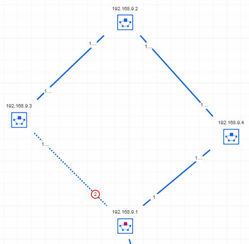
Example of a DLR topology
In the following DLR network, the device with the IP address 192.168.9.1 is the ring supervisor. All other devices are normal ring nodes. Port 2 is in blocked state.