Physical Topology Operations
This topic contains the following sections:
- Connect project devices
- Enable / disable auto placement of devices
- Enable / disable display of device graphics
- Hide / show device labels
- Hide / show connection labels
- Launch the WBM for one or several network devices
- Move / re-arrange devices
- Switch the topology layout
- Print the topology
- Filter the topology
- Zoom the view
| Further Info
For details how to capture snapshots of the network's device parameter values, see the topic "Generating Snapshots of Online Device Parameter Values". |
Connect project devices
To connect two project devices, proceed as follows:
- In the topology view, select the two devices to be connected.
- Right-click the selection and choose the context menu command 'Connect devices' (the command is only available for devices that have numbered ports). The 'Connect Devices' dialog appears. In the dialog, the devices with their port numbers are represented by their IP address.
- Select the port number for each device and click 'OK' to create the connection.
Enable / disable auto placement of devices
After scanning the network, the Ethernet devices (hereafter referred to as devices) and relating connections are positioned in the view depending on the set auto placement mode. The auto placement mode is enabled/disabled via the  button on the editor's toolbar.
With enabled auto placement (button appears pressed), new devices discovered by a network scan and online devices manually added to the project are placed automatically in the view. The editor tries to keep the position of devices that were discovered by a previous network scan.
With disabled auto placement (button appears not pressed), all devices in the view keep their position. New devices discovered by a network scan and online devices manually added to the project are placed at the top left of the view (possibly placed above each other).
For details on how to move and re-arrange devices in the view see the following section.
Enable / disable display of device graphics
The devices in the 'Physical Topology' editor and the 'Unconnected Devices' subeditor can be displayed with individual icons (device graphics) or standard icons. You can switch the display by clicking the  button in the toolbar of the 'Physical Topology' editor.
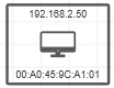
If the devices are displayed with individual icons (toolbar button appears pressed), the device icon stored in the device description file of the device (e.g., FDCML, GSDML, etc.) is shown as device symbol in the editors. The frame color indicates the device status, i.e., whether the device is only an online device, only a project device without assigned online device or an online device with assigned project device. If the FDCML files does not contain a device icon, the device-specific type icon is shown (same icon as used in the PLANT).
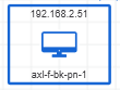 | Standard icon(Device color indicates device status) |
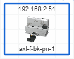 | Individual icon for the topology representation stored in the device description file of the device(Frame color indicates device status.) |
 | Device-specific type icon stored in the device description file. The icon is used if the device description file does not contain an individual icon (see above).(Frame color indicates device status.) |
Hide / show device labels
You can show or hide the device labels (e.g,. Profinet station name, MAC address, device type, etc.) for the device symbols. If enabled, the label appears in the device symbol as shown in the following example (here the MAC address of the device is displayed). If the information is not available, no value is displayed.
To choose the device label you want to display, open the 'Extras > Options' dialog and select the desired option under the 'Physical Topology | General' category. Alternatively, select a device in the topology and choose the label in the submenu of the 'Device label' context menu.
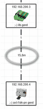
Hide / show connection labels
You can show or hide the connection labels (e.g,. media type, connection length etc.) for the connections between the network devices. If enabled, the label appears in the middle of the connection line as shown in the following example (here the connection length is displayed). If the information is not available, a question mark (?) is shown.
To choose the connection label you want to display, open the 'Extras > Options' dialog and select the desired option under the 'Physical Topology | General' category. Alternatively, select a connection line in the topology and choose the label in the submenu of the 'Connection label' context menu.
Launch the WBM for one or several network devices
To launch the web-based management (WBM) for one or several devices displayed in the topology view, select the device(s) and then click the  button on the editor's toolbar.
For each device selected in the view, the WBM is opened in a separate window or tab in your default web browser.
Move / re-arrange devices
After scanning the network, the devices and relating connections are positioned in the view depending on the set auto placement mode (see above). To manually move a device to a different location on the view, click it and drag it to the desired location. When dragging the device, the connections between the devices are automatically routed. The integrity of the topology is maintained.
To re-arrange the devices according to an internal algorithm, click the  button on the editor's toolbar.
Switch the topology layout
To switch the topology view between isometric layout and tree layout, select the corresponding entry from the list box at the top of the 'Physical Topology' editor.
The scan station (local host) that runs PLCnext Engineer is the root node of the topology by default when switching to the tree layout. To use another device in the tree as the root node, select the desired device in the topology and choose the command 'Use this device as root' from the context menu of the device.
Print the topology
- (Optional) Configure the default print settings in the 'Extras > Options' dialog under the 'Printing' category. For example, enter your company information and select a company logo. This information is printed in the footer of the printout.
- Select 'File > Print' or press <Ctrl> + <P> to open the 'Print' dialog.
- Select the 'Printer' to be used and adapt the printer 'Settings' as desired.
- In the tree, select the project items to be printed.
When deselecting a parent item, all child items are deselected too. Items with partly deselected child items are displayed with the checkbox.
 - Click the 'Print' button.
Filter the topology
The editor allows a search for specific elements. The search only operates on the graphical topology. The search text has to be entered into the 'Search' input field at the top right in the editor. The search is directly applied to the editor when entering the text. All devices that contain the search string in their device name and tooltip are highlighted by a blue rectangle.
To deactivate the search, i.e., to delete the search string entered, click the delete icon on the right of the 'Search' input field.
Zoom the view
To zoom in or out, use the zoom buttons in the status bar or press and hold the <Ctrl> key while scrolling the mouse up or down. Alternatively, click anywhere in the overview panel shown in the lower right corner and scroll the mouse up or down.