Representation of Devices, Ports and Connections
In the physical topology, the Ethernet devices (hereafter referred to as devices), ports and connections are represented by symbols and colors. Depending on the selected topology representation, there are standard device icons and port symbols that are specific to the topology. For the description of the device symbols that are specific to a specific topology view, see the corresponding description of the view in the "Topology Representations" topic.
Device symbols and labels
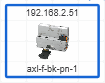
You can switch the display of the devices between two modes: standard and individual. In standard mode, the icons as listed in the following table are used for the representation of the devices. In individual mode, the device icon stored in the device description file of the device (e.g., FDCML, GSDML, etc.) is shown as device symbol. To switch the display, click the  button in the toolbar of the 'Physical Topology' editor (see also the section "Enable / disable display of device graphics" for further details).
The device label (for example, Profinet name of station, SNMP name etc.), stored in the device description file, can be optionally shown in the device symbol or hidden.
You can switch the display between different device labels or hide the labels by selecting the corresponding option in the 'Options' dialog under the 'Physical Topology | General' category or selecting the option from the context menu of the device symbol (see also the section "Hide / show device labels" for further details).
| Standard icon | Device | |
|---|---|---|
 | Scan station (local host) that runs PLCnext Engineer. | |
 | Not identified terminal device | |
 | Switch deviceA switch device is detected if the Bridge MIB is supported on the device. The Bridge MIB contains information on the Bridge port.
|
|
 | Physical router | |
 | Wireless Access PointOnly Phoenix Contact's Wireless Access Points are detected. | |
 | Wireless ClientOnly Phoenix Contact's Wireless Clients are detected. | |
 | PrinterA printer is detected if the printer MIB is supported on the network printer. The printer MIB contains information such as the description, status, or alerts about the network printer. | |
 | Wireless networkThe wireless network name (SSID = Service Set Identifier) is shown in the tooltip. The SSID uniquely identifies the wireless network. | |
 | Not identified network (for example, unmanaged switch device)The device cannot be clearly assigned to a specific device type. |
Device colors
Depending on the selected view mode (standard or individual, see the description above), the color of the device symbol or the frame color of the device symbol indicates whether the device is only an online device, only a project device without assigned online device or an online device with assigned project device. The color automatically changes when adding a device to the project or removing a device from the project.
 |  | Online device without assigned project device. |
 | Project device without assigned online device. | |
 | Online device with assigned project device. |
Port symbols
The port symbols are shown at the line ends of the connections. Whether a port operates correctly and forwards traffic or is in blocked state is displayed as shown in the following table. Depending on the selected topology representation, specific port symbols are shown. For the description of the port symbols that are specific to a specific topology view, see the corresponding description of the view in the "Topology Representations" topic.
| Symbol | Device |
|---|---|
 | Port which is operating correctly and forwarding traffic. |
 | Blocked port |
Connection types, colors and labels
The connections between the network devices are shown as follows. The color of the connection indicates whether the connection is added to the PLCnext Engineer project or not.
| Symbol / symbol color | Description |
|---|---|
 | Ethernet connectionBlack: The connection has been discovered by a network scan and then added to the project. |
 | Wireless connectionBlue: The connection has been discovered by a network scan but not yet added to the project. |
 | Redundant connectionGreen: The connection has been added to the project, but no corresponding connection has been discovered by a network scan. |
Additional notes on connections
- The ports used for the network connection are shown at the line ends. If there is a difference between an online connection (connection is not contained in the project) and an offline connection (connection has been added to the project after a network scan via the
 button on the editor's toolbar), two lines with different colors are shown.
 - Multiple connection lines between two network devices that form a Link Aggregation Group are represented as Ethernet connections (solid line). The port tooltips of the connections show information on the Link Aggregation Status and the Link Aggregation Trunk. (Link Aggregation (also called trunking) is a way of physical network linking and is the English term for the aggregation of several network connections with the aim of achieving higher transfer speeds.)
- VPN connections detected by a network scan are shown with a lock symbol.
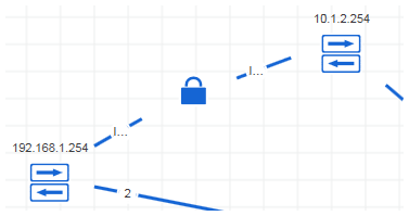
- The connection label (for example, media type, connection length etc.) can be optionally shown or hidden. If available and enabled, the label is shown in the middle of the connection line. You can switch the display between different connection labels or hide the labels by selecting the corresponding option in the 'Options' dialog under the 'Physical Topology | General' category or selecting the option from the context menu of the connection (see also the section "Hide / show connection labels" for further details).