INTERBUS Remote Bus (AXC F XT IB extension module)
This topic contains the following sections:
- General information on the extension module
- Notes and Preconditions
- AXC F XT IB extension module in logical addressing mode
- AXC F XT IB extension module in physical addressing mode
General information on the extension module
PLCnext controllers allow the connection of an AXC F XT IB extension module to the left. Via this left-alignable INTERBUS Master module, up to 255 INTERBUS remote bus devices can be integrated into an Axioline F station. The INTERBUS connection to the extension module is made via a 9-pin D-SUB socket.
PLCnext Engineer includes function blocks for starting up the INTERBUS and for the PCP communication via the bus. After having configured the INTERBUS application as described below, you have to use these FBs in your project. Refer to the respective Function Block Help for details.
| Further Info
The detailed steps for the INTERBUS startup are provided in the application note document "LEFT-ALIGNABLE INTERBUS MASTER - INTERBUS startup with the AXC F XT IB left-alignable Axioline F extension module". Enter the document number 108949_en_00 in the search field of our product website and download the manual. |
- Logical addressing modeWith this addressing mode, the INTERBUS modules are handled in the usual way in PLCnext Engineer: They can be inserted via the station editor and their process data can be assigned in the Data List.
- Physical addressing modeWith this addressing mode, no logical addressing of INTERBUS process data is possible. Instead, the physical devices are scanned at the bus and their process data are merged into a coupling memory block. Via this memory block, read/write accesses to the process data are possible in the control application.
Notes and Preconditions
- The AXC F XT IB extension module must be aligned directly left to the controller.
- When operating the INTERBUS remote bus at the PLCnext Technology controller, the local Axioline F bus can continue to be used (in contrast to the variant with the right-alignable Inline adapter terminal).
- Logical and physical INTERBUS components must be available in the project. If no INTERBUS Inline devices are provided in the 'Network' category (COMPONENTS), you have to add the 'Inline' library manually (context menu command 'Add Library...' on the 'Libraries' node in the COMPONENTS). See topic "Adding Libraries" for details.
AXC F XT IB extension module in logical addressing mode
This is the standard operation mode of the INTERBUS remote bus with connected remote bus devices. INTERBUS devices have to be added to the PLANT as usual. Their process data is then available in the Data List and can be assigned to variables in your controller application (usual logical symbolic addressing).
- In the PLANT, double-click the controller node and open the 'Settings' editor (no. (1) in the example below).
- In the 'Settings' editor, select the 'Hardware extension' category (2).
- In the editor, open the 'Interbus' drop-down list and select 'AXC F XT IB logical addressing' (3).The 'AXC F XT IB' node is now visible in the PLANT (4).
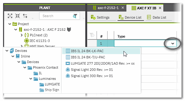
- Double-click the 'AXC F XT IB' node and open the 'Device List' editor.Add the required INTERBUS remote bus modules using the Role Picker. This procedure is described in the topic "Inserting Devices/Modules in the Station Editor".The Role Picker offers only modules with remote bus interface for selection.
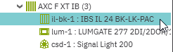
Here, an INTERBUS bus coupler (IBS IL xxx) can be inserted to which Inline modules can be connected. See step 5. - Add Inline I/O modules under bus coupler, if required.
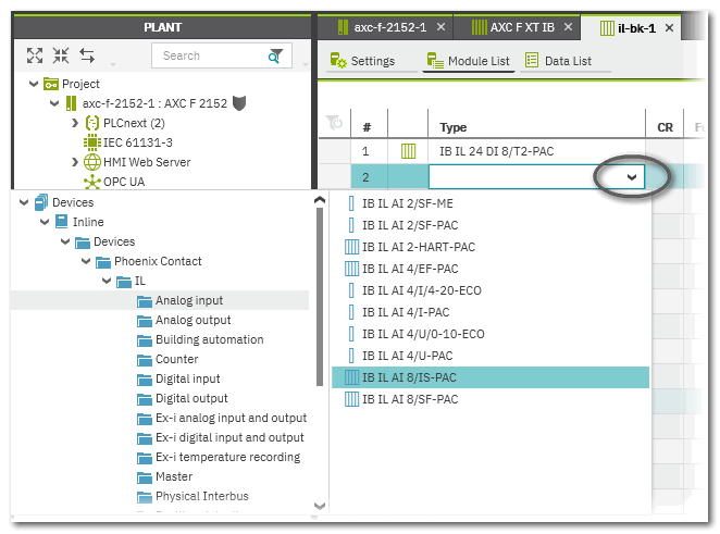
- Double-click the bus coupler node in the PLANT and open the 'Module list' editor.
- Use the Role Picker to insert I/O modules.
 Example...
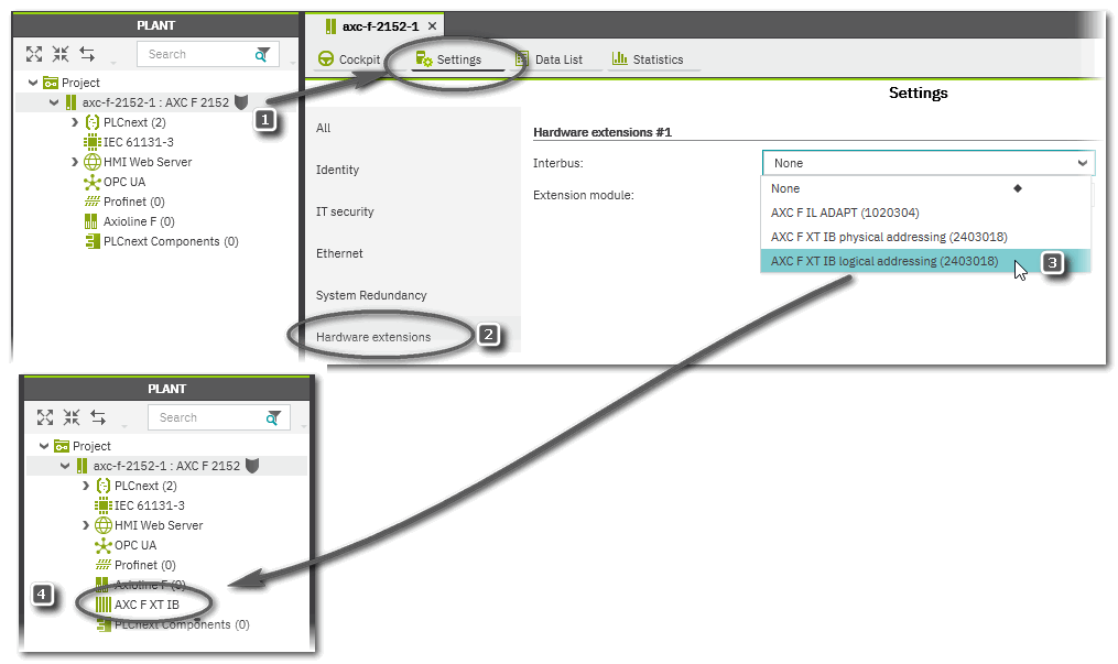
AXC F XT IB extension module in physical addressing mode
This is a special operation mode of the INTERBUS remote bus with connected local bus devices instead of remote bus devices.
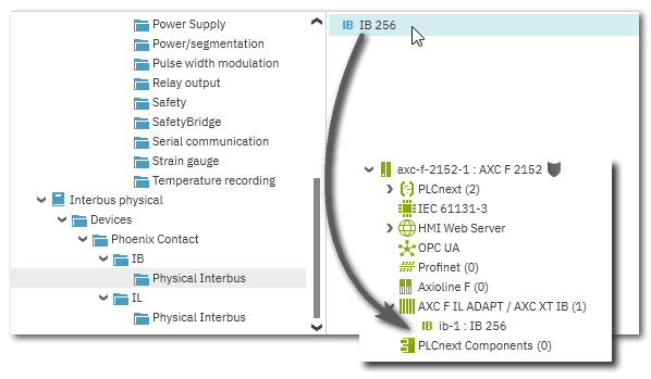
For this mode the IB 256 INTERBUS device (provided in the 'Interbus physical' library) must be available at the bus. If the INTERBUS Master detects the IB 256 device (by reading its ID code during the bus startup), the following occurs:- A bus scan is performed.
- The process data of all identified devices is automatically arranged in a memory block referred to as coupling memory. The order of the process data in the memory block corresponds to the physical device arrangement at the bus.
This coupling memory block is handed over from the INTERBUS Master to the PLCnext Technology controller. The INTERBUS process data is then accessible in the controller application and can be read/written by the application.
The bus scan and the automatic process data arrangement of physically connected bus devices gives the mode its name: physical addressing.
Due to the bus scan, it is not necessary (and not possible) to model the bus structure in the PLANT in PLCnext Engineer. Instead, only the IB 256 device must be inserted below the 'AXC F XT IB' node. After the scan, the found devices are not listed in the PLANT.
Another characteristic of this mode is that the process data of the scanned modules are not available in the Data List (in order to assign them to variables there). Instead, direct read and write accesses to the coupling memory area must be programmed in the control application (no logical, symbolic addressing). For this purpose, the structure and the individual addresses of the process data must be known.
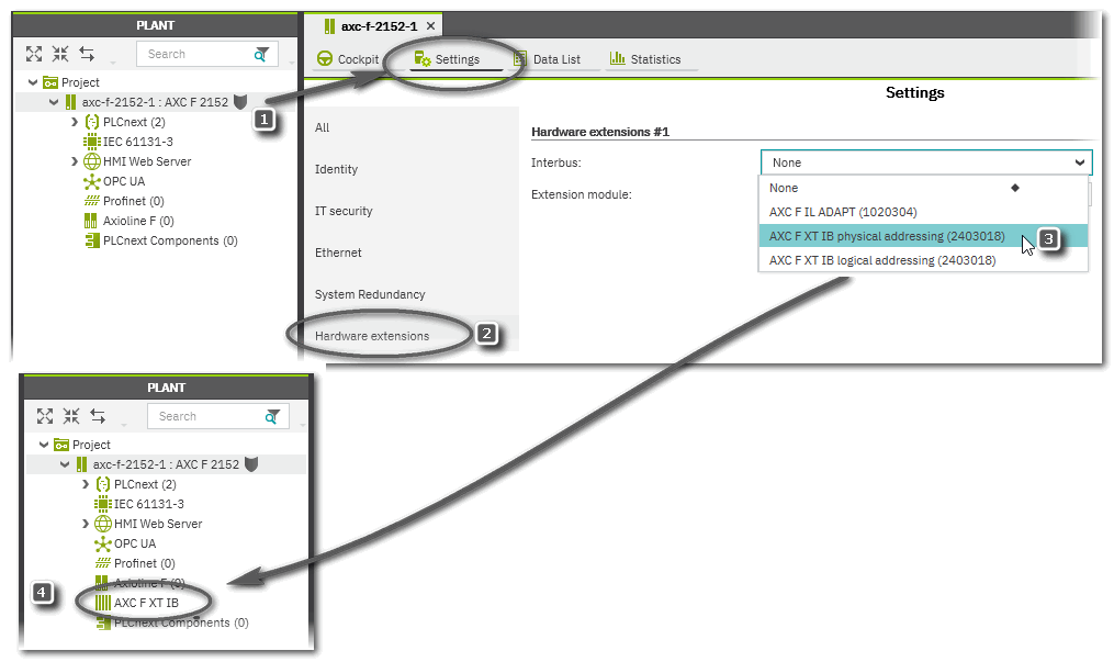
- In the PLANT, double-click the controller node and open the 'Settings' editor (no. (1) in the example below).
- In the 'Settings' editor, select the 'Hardware extension' category (2).
- In the editor, open the 'Interbus' drop-down list and select 'AXC F XT IB physical addressing' (3).The 'AXC F XT IB' node is now visible in the PLANT (4).
- Double-click the 'AXC F XT IB' node and open the 'Device List' editor.Add the IB 256 module using the Role Picker. This procedure is described in the topic "Inserting Devices/Modules in the Station Editor".
- The IOs are represented as Octetstring[256] input/output arrays and must be assigned to the corresponding variables/ports in your project.