HMI Alarming Example
This example shows how to configure an alarming system and how to use an HMI Symbol List and user-defined HMI symbol to visualize the alarms in the HMI application.
In the first step, we use the 'Alarm Server | Alarms' editor to define the alarm, i.e., select the signal to be monitored in the application and configure the basic properties of the alarm (see the topic "Alarming" for a detailed description of the alarm properties). In the second step, we create an HMI symbol named AlarmRow. The AlarmRow symbol represents an alarm and its properties within the alarming system. In the last step, we configure a Symbol List named AlarmTable. The symbol list represents the alarm table showing the alarms reported by the alarming system. The AlarmTable uses the AlarmRow symbol as symbol instance.
This topic contains the following sections:
- Step 1: Define the alarm
- Step 2: Create the AlarmRow symbol
- Step 3: Create the AlarmTable symbol list
Step 1: Define the alarm
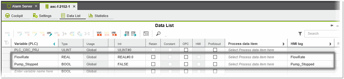
In this example we monitor the flow rate of a pump using the application variable 'FlowRate' to detect the alarm condition. An alarm will be generated when the 'FlowRate' value goes below the value of 10 percent (LowLow alarm type). If the pump is off (value of the boolean variable 'Pump_Stopped' is true), the alarm is suppressed.
Proceed as follows:
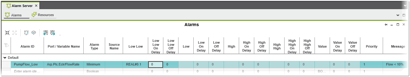
- Open the 'Alarms' editor of the 'Alarm Server' PLANT node. In the 'Alarms' editor, enter the following alarm properties (irrelevant alarm properties are omitted):
Property Value Description Alarm ID PumpFlow_Low Unique name of the alarm (must not contain blanks or special characters). Port / Variable Name Arp.Plc.Eclr/FlowRate Variable 'FlowRate' that is monitored. Alarm Type Minimum The 'FlowRate' is compared to the 'LowLow' limit. If the value drops below the limit, the alarm is triggered. The alarm remains active until the value exceeds the 'LowLow' limit. LowLow REAL#0.1 The alarm will be triggered when the 'FlowRate' is lower than or equal to 10 percent. The alarm remains active until the value exceeds the limit. Priority 1 Alarm priority (1 = lowest alarm priority). Message Flow < 10% Text that will be shown to the operator in the HMI application when the alarm is active. Description Pump flow is below operating threshold Description that will be shown to the operator in the HMI application when the alarm is active. Access Rights:'Acknowledge Required''Confirm Required' 'Suppression Allowed' All checkboxes activated Actions that the operator must take when an alarm is active. - 'Acknowledge Required'The operator must acknowledge the alarm to set the alarm to the acknowledged state.
- 'Confirm Required'The operator must confirm the alarm to set the alarm to the confirmed state.
- 'Suppression Allowed'Alarm can be suppressed, i.e., the alarm will not be shown to the operator, but the alarm is still present in the system (see the following property).
Suppress Condition Variable Name Arp.Plc.Eclr/Pump_Stopped The alarm is suppressed (not shown to the operator), if the boolean variable 'Pump_Stopped' (pump is off) has the value true. Enabled Activated The evaluation of the alarm will be processed. - Assign a program instance of type 'AlarmProgram' to a task in the 'Tasks and Events' editor.(A program instance of type 'AlarmProgram' (available by default) must be assigned to a task to create a valid alarm configuration.)
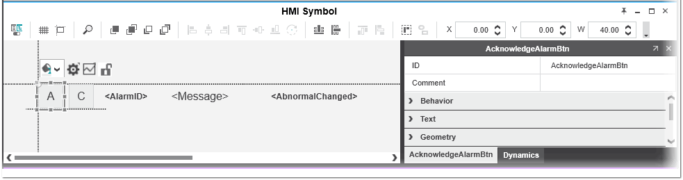
Step 2: Create the AlarmRow symbol
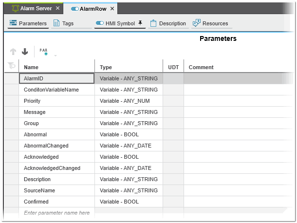
The AlarmRow symbol represents the alarm and its properties. It is used as symbol instance for the AlarmTable Symbol List. Each AlarmRow symbol represents an alarm. The symbol parameters will be bound to the alarm array fields when instantiated in the AlarmTable to get access to the global list of alarms and their properties and values.
Proceed as follows:
- Create an HMI symbol.Right-click the 'Local' folder in the 'HMI' category in the COMPONENTS area and select 'Add HMI Symbol' from the context menu. Rename the symbol to 'AlarmRow'.
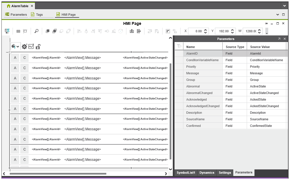
- In the 'Parameters' editor, add the following symbol parameters (will be bound to the alarm array fields when instantiated in the AlarmTable symbol list).
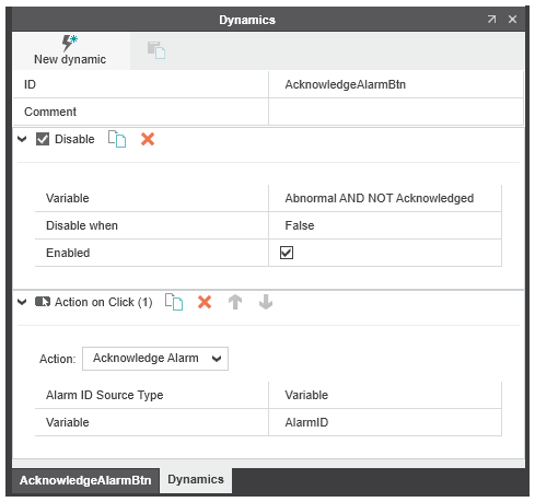
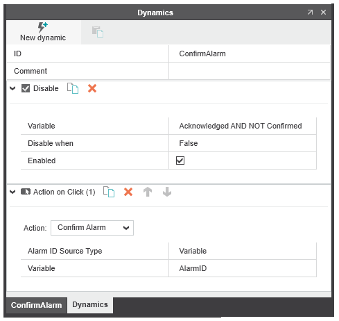
- In the 'HMI Symbol' editor, add the following HMI symbols and assign the dynamics to the symbols:
 'A' (Acknowledge) button - triggers the acknowledgment of the alarm
'C' (Confirm) button - triggers the confirmation of the alarm
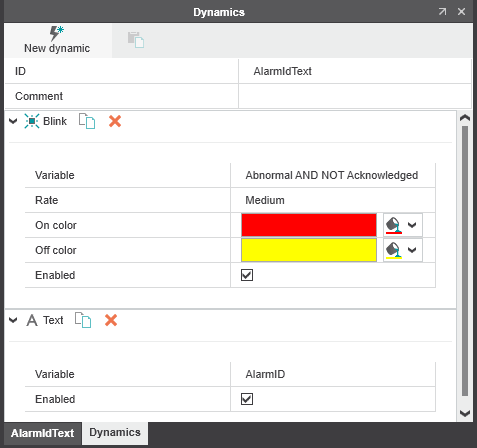
Text object - displays the AlarmID at runtime and blinks dependent on the alarm state
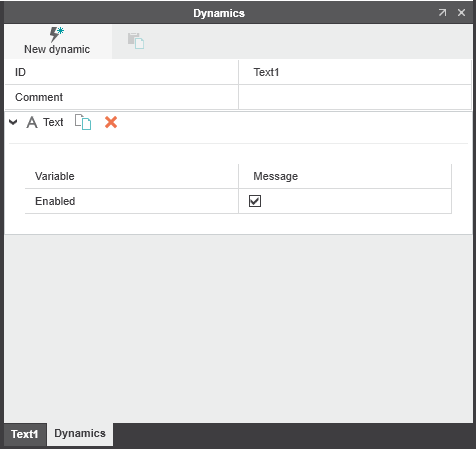
Text object - displays the alarm message text
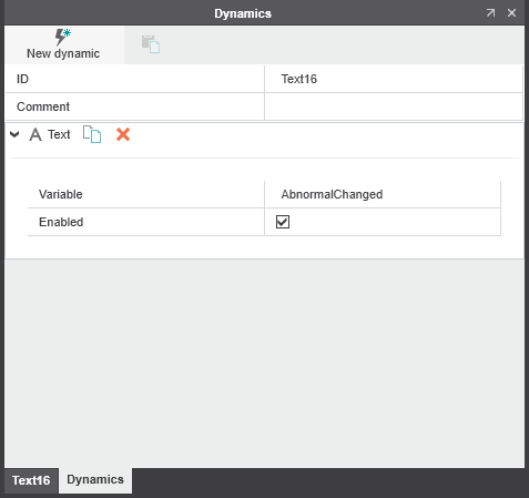
Text object - displays the date and time when the alarm state last changed
'A' (Acknowledge) button - triggers the acknowledgment of the alarm
'C' (Confirm) button - triggers the confirmation of the alarm
Text object - displays the AlarmID at runtime and blinks dependent on the alarm state
Text object - displays the alarm message text
Text object - displays the date and time when the alarm state last changed
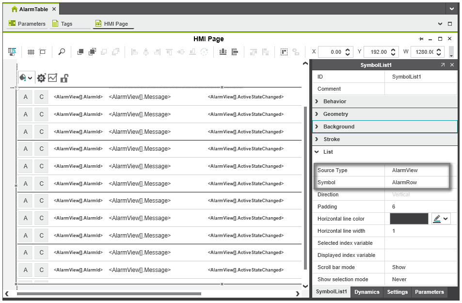
Step 3: Create the AlarmTable symbol list
The AlarmTable symbol list shows the alarms reported by the alarming system at runtime. Each row in the AlarmTable is represented by an own AlarmRow symbol (see above).
The connection to the alarming system is done by binding the symbol parameters defined for the AlarmRow to the alarm array fields.
Proceed as follows:
- Create a new HMI page and drag an HMI symbol list from the 'HMI | Objects' category in the COMPONENTS area into the page.
- In the 'Properties' tab of the symbol list, open the 'List' group and set the 'Source Type' to 'AlarmView' and select the 'AlarmRow' symbol for the 'Symbol' parameter.With the 'AlarmView' source type you get access to the alarm array fields (see the following step) which contain all alarm information queried from the alarm source at runtime.
- Go to the 'Parameters' tab of the symbol list. The 'Name' column contains all symbol parameters that we have defined for the AlarmRow symbol (see the previous step).Assign a value to each parameter. For each parameter, select the 'Source Value'. The 'Source Value' drop-down list provides the alarm array fields for selection (the drop-down list only shows the array elements of matching data types).