Adding Devices by Importing Device Description Files
This topic contains the following sections:
- Adding Profinet devices by importing device description files (*.GSDML)
- Adding bus devices by importing field device configuration files (*.FDCML)
- Adding IO-Link devices by importing IO Device Description files (*.IODD)
Adding Profinet devices by importing device description files (*.GSDML)
Profinet devices can be added to the project via libraries or by importing a device description file (*.GSDML).
Conversion of process data (byte ordering) when importing from GSDML
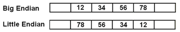
Profinet uses the big endian format as byte order (endianness) for the representation of data items. This means, in a multi-byte value the first byte corresponds to the most significant byte (MSB) and the last byte represents the least significant byte (LSB). On the other hand, in little endian, the first byte corresponds to the LSB and the last byte to the MSB.
The following example shows how a 4 byte value of 0x12345678 is represented in big endian and little endian format. In big endian, the value 0x12 is the most significant byte and placed at the lowest position. In little endian, the value 0x78 is the least significant byte and placed at the lowest position.
In the GSDML file, the process data items are described using the <DataItem> element. If the element's optional attribute "UseAsBits" is set to true (only for the unsigned data type variants; see below), PLCnext Engineer is allowed to represent (display) the process data as individual bits. This means, for each bit within the <DataItem> element, a corresponding IN0...INx respectively OUT0...OUTx process data item is generated.
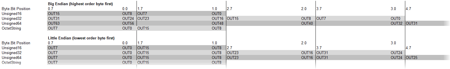
By default (as of PLCnext Engineer 2023.0), PLCnext Engineer uses the big endian format for the creation and representation of I/O bit data items when importing Profinet devices via GSDML files. This means, the data items are counted (numbered incrementally) and named from zero, where zero represents the most significant bit (first bit within a byte data item = most significant bit). For example, for an output of data type UNSIGNED16, the bit data items OUT00...OUT15 are created, where OUT00 is mapped to the byte.bit position 1.0 and OUT15 to position 0.7. On the other hand, in little endian format, OUT00 is mapped to the byte.bit position 0.0 and OUT15 to position 1.7. The following illustration shows how the bit data items (only relevant for unsigned data types) are imported and represented in PLCnext Engineer (output data item used as example).
The endianness to be used for the process data conversion can be configured in the 'Extras > Options' dialog under the 'GSDML Import | GSDML Import Settings' category. With 'Recommended Profinet Endianness' set to 'Yes' (default setting), big endian is used when importing. With 'No', little endian is used for the data conversion and representation (see the following note).
| Note
Behavior in earlier versions than PLCnext Engineer 2023.0 In earlier versions than PLCnext Engineer 2023.0, little endian is used by default for the conversion of process data when importing Profinet devices. This means, the data items were counted from zero, where zero represents the least significant bit. When re-importing Profinet devices into your project due to any file modifications, ensure that the same endianness conversion as used for the initial import is configured in the 'Extras > Options' dialog. If the GSDML file is not re-imported with the same endianness, the process data are read and mapped in reverse order. |
Example: Little endian and big endian representation of data items
| Big endian representation ('Recommended Profinet Endianness' = 'Yes') 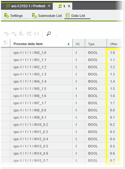 | Little endian representation ('Recommended Profinet Endianness' = 'No') 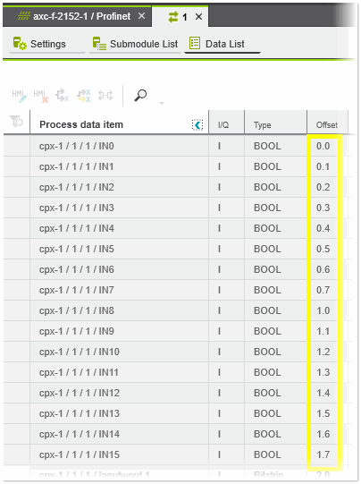 |
| Note
Bit offset The 'Offset' of a process data item shown in any Data List indicates where the start bit of the data item is located. The offset is specified as Byte.Bit, where the offset 0.0 indicates the least significant bit within the byte. In case of big endian representation, the offset is also appended to the data item label (see the example above). |
Proceed as follows:
- In the 'Extras > Options' dialog under the category 'GSDML Import', select which Profinet endianness (big or little endian) you want to use for the device import (see the description above).
- Select 'File > Import > Import GSDML File(s)...'.
- In the appearing browse dialog, select the device descriptions to be imported and click 'Open'.
After importing the device descriptions, these devices are available in the 'Local' folder of the 'Network' category (COMPONENTS area).
Adding bus devices by importing field device configuration files (*.FDCML)
Field devices can be added to the project via libraries or by importing a device description file (*.FDCML).
- Select 'File > Import > Import FDCML File(s)...'.
- In the appearing browse dialog, select the device descriptions to be imported and click 'Open'.
After importing the device descriptions, these devices are available in the 'Local' folder of the 'Network' category (COMPONENTS area).
Adding IO-Link devices by importing IO Device Description files (*.IODD)
IO-Link devices can be added to the project by importing an IO Device Description file (*.IODD).
- Select 'File > Import > Import IODD File(s)...'.
- In the file open dialog, select one or several IODD files you want to import and click 'Open'.If the IODD file contains several device variants, an 'Import' dialog appears. The dialog shows every device variant contained in the selected IODD file as a single entry. For each device variant to be imported, activate the corresponding checkbox in the 'Import' column. To select/deselect all checkboxes, select the corresponding command from the context menu of the 'Import' column. Click on 'OK' to import the selected variants. The corresponding devices and their variants, if selected, are added to the 'Local > Devices' folder under the 'Network' category in the COMPONENTS area (observe the following note). The project log in the MESSAGES window informs you if the import was successful or if there were any errors.
Note
There are always two device types added to the COMPONENTS area when importing an IODD file: one device under the AXLF subfolder and one device under der PN subfolder. The reason for this is because the different network protocols (Profinet and Axioline) have different mechanisms for IO-Link integration. However, when assigning IO-Link devices to the master ports using the master's 'Submodule List' editor, the Role Picker only provides the devices for selection that match the corresponding network protocol.
| Further Info
See the topics "IO-Link Configuration for Axioline and Profinet" for details on the configuration of an IO-Link system. |