PLANT Area
This topic contains the following information:General information
The PLANT area at the left of the PLCnext Engineer user interface contains a tree which models the application. Its hierarchical structure contains nodes which represent the physical and logical components (hardware and software) of the plant/machine to be controlled. Physical components are the controller, devices and I/O modules. Logical components are, for example, the PLCnext node where the runtime can be configured and ports can be assigned to each other, or the 'IEC 61131-3' node where the data mapping has to be done.
An included embedded OPC UA server is shown as separate tree node in the PLANT.
Via this 'OPC UA' PLANT tree node, also OPC UA PubSub communication can be configured if supported by the PLCnext Technology controller (only with a firmware version 22.0 or newer).
If a Safety PLC is included it also has its own icon in the tree.
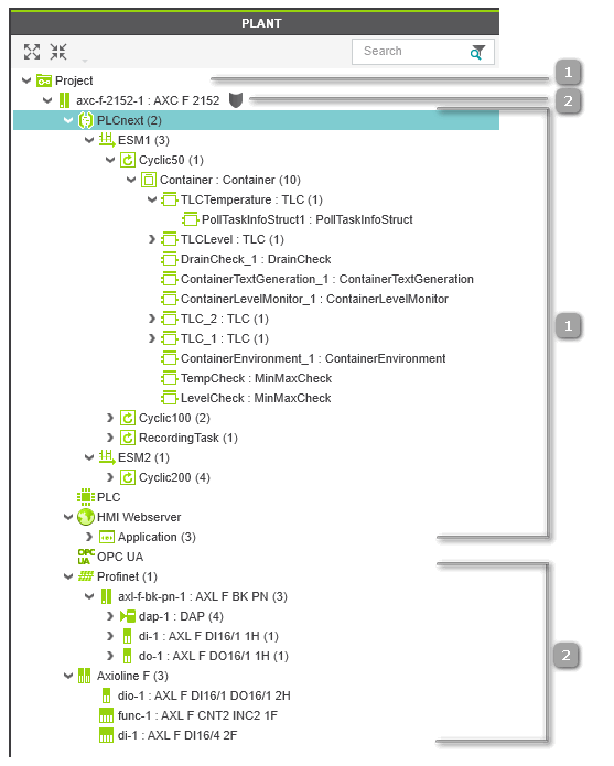
 Example: engineering project for AXC F 2152 controller, Profinet modules and Axioline devices
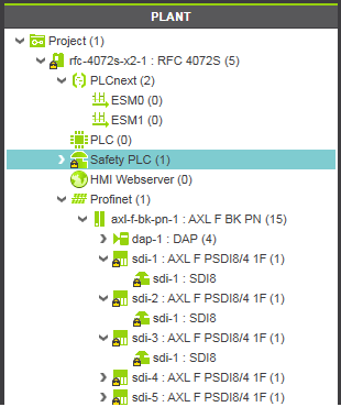
Example: Safety PLC integrated in controller
Secure devices: shield icon indicates logon status for PLCnext Technology controllers


 | Use these buttons on the main toolbar or commands in the 'View' menu, to show or hide particular objects in the PLANT. |
| Note
Even if Profinet System Redundancy is realized in your solution, the PLANT contains only one controller node, which is the primary controller. The backup controller is not visible in the PLANT. Refer to the help chapter "Profinet Redundancy ×‣ Profinet System Redundancy (SR) ×" for details. |
PLANT implements the model of configuration elements according to IEC 61131-3
An IEC 61131-3-compliant programming system reflects the application structure by IEC 61131-3 configuration elements. These configuration elements are basically configurations, resources and tasks.In PLCnext Engineer, the IEC 61131-3 model is implemented as follows.
- The controller is considered as configuration. Currently, one configuration acc. to IEC 61131-3 is supported, i.e., one controller node is allowed in a project.
- The controller runtime is considered as resource. Currently, one resource acc. to IEC 61131-3 is supported, i.e., one 'PLCnext' node is allowed in a project.
- Tasks have to be configured in the controller runtime properties. For that purpose, the 'PLCnext' node in the PLANT can be doubled-clicked to configure tasks and program instances. Refer to the topic "Controller runtime configuration" for details.
- If a Safety PLC is included in your application, the standard controller and the Safety PLC are strictly separated. Each of it executes its own application, has its own global variables, and its own runtime configuration. Therefore, the Safety PLC is represented by its own icon in the PLANT. Refer to the topic "Safety PLC runtime configuration" for details.
| Note
If non-IEC 61131-3 programs (from PLCnext Technology libraries) are instantiated, they are also visible under the 'PLCnext' node like IEC programs. |
Background: configuration elements according to IEC 61131-3
PLANT contains instances of component types
Basically, the PLANT contains instances of the components provided in the COMPONENTS area on the right. These components are considered as types. By inserting a type from one of the categories of the COMPONENTS area into the PLANT (e.g., via drag & drop), the type is instantiated in the project.
Safety-related devices are marked by the  overlay icon.
When editing the properties or content of a type provided in the COMPONENTS area, the reusable type itself is modified and, as a result, each existing or future instance of this type is affected by the modification. In contrast, editing an instance of a type in the PLANT (for example by parameterizing a device), only this particular instance is affected, but the type in the COMPONENTS area remains unmodified.
Editing PLANT node properties
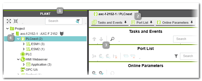
By double-clicking a PLANT tree node, its properties are opened and can be modified in a group of editors which appear in the editors area. The number and style of the available editors depend on the node type.
To be able to edit safety-related data, you have to be logged on to the Safety-related Area. Refer to the topic "Safety-Related Area with Password Protection" for details.
The topic "PLANT Tree Node Editors" describes all available editors.
If the controller involved implements a secure device concept, the shield symbol beside the controller icon indicates the current logon status to the controller. In this case, node properties can only be edited, if you are logged on to the controller (green shield). Refer to the topic "Network Security" for details.
For an FB instance, you can directly jump to the call of the function block in the relating code worksheet using the 'Cross References' context menu command. The submenu of the 'Cross References' context menu command of an FB instance contains the code worksheet where the FB instance is used. (The command is only active, if the cross references are collected and up-to-date in the "CROSS REFERENCES Window".)
Also refer to the topic "Editors area" and to the procedure list below.
IEC 61131-3-compliant instance tree (in programming mode and debug mode)
The 'PLCnext' node contains the runtime configuration (task/event specification).
When expanding this node, it corresponds to the instance tree according to the IEC 61131-3 standard: the controller runtime as resource contains tasks in which program instances are executed. Function block calls in programs appear as FB instances.
Under the 'PLCnext' node, the controller cores are separated and, for each core, the specified tasks, program instances, and function block instances (according to the IEC 61131-3 standard). Instances of non-IEC 61131-3 programs (from an included PLCnext Technology components library) are also listed here.
| Note
After inserting an FB instance into a program POU, the instance structure in the PLANT is automatically updated after the next run of the background check. |
In programming mode, double-clicking the 'PLCnext' node opens the node properties. You can insert tasks/events and create program instances (see procedure below). Double-clicking a program/FB instance in the PLANT opens the Data List or GDS Port List of this instance in the editors area.
For an FB instance, you can directly jump to the call of the function block in the relating code worksheet using the 'Cross References' context menu command. The submenu of the 'Cross References' context menu command of an FB instance contains the code worksheet where the FB instance is used. (The command is only active, if the cross references are collected and up-to-date in the "CROSS REFERENCES Window".)
In debug mode, if PLCnext Engineer is attached to the running application process and a controller status is shown at the controller icon, double-clicking an instance node opens the online code for the corresponding instance (instead of using the 'Go To Instance Editor' context menu command in code worksheets).
The Safety PLC executes exactly one task in which exactly one program must be instantiated.
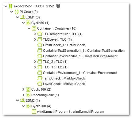
Example: instance
representation under the 'PLCnext' node for a AXC F 2512 controller type
What do you want to do?
 Networking: structuring the application by inserting network devices (manually or by network scan)
 ![]() ‣ Online: Scan Network to add Devices to PLANT
‣ Online: Scan Network to add Devices to PLANT
×‣ Offline: Add Devices manually to PLANT
×
Profinet controller/Profinet device parameterization
Axioline F controller/Axioline device
parameterization
Controller runtime configuration: task/event definition, program instantiation