|
Short Description
| The safety-related SF_MutingSeq function block evaluates the signals of four muting sensors and an optoelectronic safety-related equipment (a light grid, for example) in an application for sequential muting with four sensors and switches the enable signal at the S_AOPD_Out output.The signal at the S_AOPD_Out output is the enable signal for the entire process. A SAFEFALSE signal at the S_AOPD_Out output stops the application in the zone of operation.This function can be used to temporarily deactivate (or "mute") safety-related equipment in the form of a light grid, for example, in order to allow an object which has been identified by the muting sensors as permissible (for the muting operation) to pass through on an assembly conveyor.In such a case, the interruption of the light grid does not have any effect on the S_AOPD_Out output.By contrast, if the safety-related equipment is engaged by an object which has not been identified by the muting sensors as permissible, the S_AOPD_Out output switches to SAFEFALSE.
For example, if the hand of a worker passes through an assembly conveyer interrupting a light grid, the S_AOPD_Out output would be used to signal the actions necessary to set the zone of operation to its defined safe state.The maximum allowable time for the muting operation is monitored using the four muting sensors. Please refer to the following representation to view the arrangement of the muting sensors.In the event of a muting error, the safety-related shutdown requested by the safety function can be temporarily deactivated by means of the integrated override function, e.g., in order to move an impermissible object which caused the muting error outside the zone of operation. The override function must be manually requested by the operating personnel as long as the object is in a safeguarded area or the override function has been automatically exited. A start-up inhibit can be specified at S_StartReset.
Hinweis
Depending on the result of the risk analysis, optical, mechanical or inductive sensors such as reflection light sensors, mechanical or inductive switches can be used as muting sensors. Optical sensors serve as examples in the help information. |
Hinweis
Only the material flow direction from muting sensors S_MutingSwitch11 S_MutingSwitch12 to muting sensors S_MutingSwitch21S_MutingSwitch22 is described in the following (forward direction). The function block also supports the opposite material flow direction from muting sensors S_MutingSwitch22S_MutingSwitch21 to muting sensors S_MutingSwitch12S_MutingSwitch11 (backwards direction). The functional sequence remains identical. S_MutingSwitch12 to muting sensors S_MutingSwitch21S_MutingSwitch22 is described in the following (forward direction). The function block also supports the opposite material flow direction from muting sensors S_MutingSwitch22S_MutingSwitch21 to muting sensors S_MutingSwitch12S_MutingSwitch11 (backwards direction). The functional sequence remains identical. |
|
| Illustration of Application | The following graphic illustrates an application for the SF_MutingSeq function block.
Weitere Infos
The entire muting operation is divided into different muting sequences. For more detailed information (including override), see the functional description. |
 The material flow direction in the example shown is from left to right.
MS_11, MS_12: First sequential muting sensor pair, positioned before the safety-related equipment connected to the function block inputs S_MutingSwitch11 and S_MutingSwitch12 (the "yellow light beams" symbolize the detection area).
The material flow direction in the example shown is from left to right.
MS_11, MS_12: First sequential muting sensor pair, positioned before the safety-related equipment connected to the function block inputs S_MutingSwitch11 and S_MutingSwitch12 (the "yellow light beams" symbolize the detection area).
MS_21, MS_22: Second sequential muting sensor pair, positioned behind the safety-related equipment, connected to function block inputs S_MutingSwitch21 and S_MutingSwitch22.
S, R: Transmitter and receiver of the light grid (safety-related equipment)
KS: Control device (e.g., key switch) for override
T: Goods to be transported on an assembly conveyor
!: Zone of operation |
|
Block Icon
| 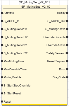 |
|
Inputs
|  Activate Activate
| Short description | Value |
State-controlled input for activating the function block. Data type: BOOL
Initial value: FALSE |
-
FALSE: Function block inactive.
-
TRUE: Function block activated.
|
Refer to the topic "Activate" for details.
S_AOPD_In
| Short description | Value |
State-controlled input for the status of the safety-related equipment (e.g., light grid).Data type: SAFEBOOL
Initial value: SAFEFALSE |
-
SAFEFALSE: Light beam of the optoelectronic safety-related equipment (e.g., light barrier) interrupted.
Hinweis
The S_AOPD_Out output becomes SAFEFALSE when the muting operation is not active and override is not requested (S_MutingActive = SAFEFALSE and OverrideActive = FALSE). |
-
SAFETRUE: Light beam of the optoelectronic safety-related equipment (e.g., light barrier) not interrupted.
|
Refer to the topic "S_AOPD_In" for details.
S_MutingSwitch11 and S_MutingSwitch12
| Short description | Value |
State-controlled inputs for the muting sensors of the first sequential sensor pair.Data type: SAFEBOOL
Initial value: SAFEFALSEFor the material flow direction
- from left to right, both of these sensors are positioned before the safety-related equipment.
- from right to left, both of these sensors are positioned behind the safety-related equipment.
|
-
SAFEFALSE: Light beam of the muting sensor not interrupted
-
SAFETRUE: Light beam of the muting sensor interrupted
|
Refer to the topic "S_MutingSwitch11 and S_MutingSwitch12" for details.
S_MutingSwitch21 and S_MutingSwitch22
| Short description | Value |
State-controlled inputs for the muting sensors of the second sequential sensor pair.Data type: SAFEBOOL
Initial value: SAFEFALSEFor the material flow direction
- from left to right, both of these sensors are positioned behind the safety-related equipment.
- from right to left, both of these sensors are positioned before the safety-related equipment.
|
-
SAFEFALSE: Light beam of the muting sensor not interrupted
-
SAFETRUE: Light beam of the muting sensor interrupted
|
Refer to the topic "S_MutingSwitch21 and S_MutingSwitch22" for details.
MaxMutingTime
| Short description | Value |
Specification of the maximum permissible time for the entire muting operation.Data type: TIME
Initial value: #0msIf the muting operation is not completed within this time, the S_AOPD_Out output is switched to the defined safe state SAFEFALSE (e.g., "switch off machine").The following is valid for a material flow direction from left to right:
- This timer starts when the first muting sensor before the safety-related equipment (at input S_MutingSwitch11) provides a SAFETRUE signal (i.e., there is an object inside the detection area of the sensor).
- The muting operation is complete when the first muting sensor behind the safety-related equipment (at the S_MutingSwitch21 input) provides SAFEFALSE again.
The following is valid for a material flow direction from right to left:
- This timer starts when the first muting sensor before the safety-related equipment (at input S_MutingSwitch22) provides a SAFETRUE signal (i.e., there is an object inside the detection area of the sensor).
- The muting operation is complete when the first muting sensor behind the safety-related equipment (at the S_MutingSwitch12 input) provides SAFEFALSE again.
| Minimum value: 0 s
Maximum value: 120 mEnter a time value according to your risk analysis.Refer to the first warning below this table. |
Non-conformance to safety function requirements
- Verify that the time value set at the time input corresponds to your risk analysis.
- Be sure that your risk analysis includes an evaluation for incorrectly setting the time value at the time input.
- Validate the overall safety-related function with regard to the set time value and thoroughly test the application.
|
Refer to the topic "MaxMutingTime" for details.
MaxOverrideTime
| Short description | Value |
Specification of the maximum permissible time for the override operation.Data type: TIME
Initial value: #60ms If the override operation is not completed within this time, the S_AOPD_Out output is switched to the defined safe state SAFEFALSE (e.g., "switch off machine").This timer starts with the state SAFETRUE at the S_StartStopOverride input by activating the connected control device.The override operation is complete when:
- the override operation is interrupted by the operator
- or all muting sensors provide SAFEFALSE again and the light beam of the safety-related equipment is no longer interrupted.
| Minimum value: 0 s
Maximum value: 600 sEnter a time value according to your risk analysis. |
Non-conformance to safety function requirements
- Verify that the time value set at the time input corresponds to your risk analysis.
- Be sure that your risk analysis includes an evaluation for incorrectly setting the time value at the time input.
- Validate the overall safety-related function with regard to the set time value and thoroughly test the application.
|
Refer to the topic "MaxOverrideTime" for details.
MutingEnable
| Short description | Value |
State-controlled input for enabling the muting operation.Data type: BOOL
Initial value: FALSE |
-
FALSE: No enable for the muting operation
-
TRUE: Enable for the muting operation
|
Refer to the topic "MutingEnable" for details.
S_StartStopOverride
| Short description | Value |
State-controlled input for the start of the override operation by the operator.Data type: SAFEBOOL
Initial value: SAFEFALSE
Hinweis
If the override operation is interrupted, although the muting error still exists, the output S_AOPD_Out switches to SAFEFALSE and output Error to TRUE. |
Hinweis
The S_StartStopOverride input has no effect if the requirements for the override function are not met (output OverridePossible = FALSE). |
|
-
SAFEFALSE: The override function is not requested
-
SAFETRUE: The override function is requested
|
Refer to the topic "S_StartStopOverride" for details.
S_StartReset
| Short description | Value |
State-controlled input for specifying the
start-up inhibit after the Sicherheitssteuerung has been started up or the function block has been activated.An active
start-up inhibit must be removed manually by means of a positive signal edge at the Reset input. A deactivated
start-up inhibit causes the S_AOPD_Out output to switch to SAFETRUE automatically when the function block is activated and the safety-related function is not requested.Data type: SAFEBOOL
Initial value: SAFEFALSE |
-
SAFEFALSE: With
start-up inhibit
-
SAFETRUE: Without
start-up inhibit
|
Non-conformance to safety function requirements
- Be sure that your risk analysis includes an evaluation if the start-up inhibit is deactivated (S_StartReset = SAFETRUE).
- Observe the regulations given by relevant sector standards regarding the start-up inhibit.
- Verify that a suitable start-up inhibit is in place at another location or using other means if the start-up inhibit is deactivated by setting S_StartReset = SAFETRUE.
|
Refer to the topic "S_StartReset" for details.
Reset
| Short description | Value |
Edge-triggered input for the reset signal:
- Resetting error messages when the cause of the error is no longer present.
- Manual resetting of an active start-up/restart inhibit (depending on which type(s) of inhibit the function block provides).
Data type: BOOL
Initial value: FALSE |
-
FALSE: Reset is not requested
- Edge FALSE > TRUE: Reset is requested
|
Hinweis
Resetting does not occur with a negative (falling) edge, as specified by standard EN ISO 13849-1, but with a positive (rising) edge.
To implement the reset with a falling edge (with regard to the mandatory acceptance procedure), use the function block SF_Reset. |
Resetting the function block by means of a positive signal edge at the Reset input can cause the S_AOPD_Out output to switch to SAFETRUE immediately (depending on the status of the other inputs).
Unintended start-up
- Include in your risk analysis the impact of the reset by means of a positive signal edge at the Reset input.
- Make certain that appropriate procedures and measures (according to applicable sector standards) have been established to help avoid hazardous situations when resetting.
- Do not enter the zone of operation when resetting.
- Ensure that no other persons can access the zone of operation when resetting.
- Use appropriate safety interlocks where personnel and/or equipment hazards exist.
|
Refer to the topic "Reset" for details.
|
|
Outputs
| Ready
| Short description | Value |
| Output for signaling "Function block activated/not activated".Data type: BOOL |
-
FALSE: Function block is not activated (Activate = FALSE) and all outputs of the function block are switched to FALSE/SAFEFALSE.
-
TRUE: Function block is activated (Activate = TRUE) and the output parameters represent the state of the safety-related function.
|
Refer to the topic "Ready" for details.
S_AOPD_Out
| Short description | Value |
| Output for enable signal of the function block.Data type: SAFEBOOL |
-
SAFEFALSE:
- The muting or override operation is not active and the light grid detects an object
-
or the muting operation is active and the function block detects an error (and override is not requested)
-
or the override operation is interrupted and the function block detects an error
-
or the function block is not activated
-
or the start-up inhibit is active.
-
SAFETRUE:
- The muting operation is not active and the light grid does not detect an object
-
or override is requested
-
or the muting operation is active and the function block does not detect an error.
|
Refer to the topic "S_AOPD_Out" for details.
S_MutingActive
| Short description | Value |
| Output for the status of the muting operation.Data type: SAFEBOOL |
-
SAFEFALSE:
- The muting operation is not active
-
or the function block is not activated
-
or the start-up inhibit is active
-
or an error message is present.
-
SAFETRUE:
- The muting operation is active
-
and the function block is activated
-
and the start-up inhibit is not active
-
and no error message is present.
|
Refer to the topic "S_MutingActive" for details.
OverridePossible
| Short description | Value |
| Output for the monitoring signal providing notification that an override operation is possible: signals whether override can be requested by the operator (TRUE) or not (FALSE).Data type: BOOL |
-
FALSE:
- The function block does not detect any muting errors
-
or the light grid does not detect an object
-
or no muting sensor detects an object
-
or the function block is not activated.
-
TRUE:
- The function block detects a muting error
-
and the light grid detects an object
-
and at least one muting sensor detects an object
-
and the function block is activated.
|
Refer to the topic "OverridePossible" for details.
OverrideActive
| Short description | Value |
| Output for the status of the override operation.Data type: BOOL |
-
FALSE:
- Override is not requested or already completed
-
or override is not possible (OverridePossible = FALSE)
-
or override timer (MaxOverrideTime) elapsed
-
or the function block is not activated
-
or the startup inhibit is active
-
or an error message is present.
-
TRUE:
- Override operation active (S_StartStopOverride input = SAFETRUE)
-
and override timer (MaxOverrideTime) has not yet been elapsed
-
and the function block is activated
-
and the startup inhibit is not active
-
and no error message is present.
|
Refer to the topic "OverrideActive" for details.
SafetyDemand
| Short description | Value |
Output for signaling "safety-related function requested".
This output displays whether the safety chain is interrupted and as a result, the attention of the operator is required. Data type: BOOL |
-
FALSE: Safety-related function is not requested.
-
TRUE: The safety-related function is requested.
|
Refer to the topic "SafetyDemand" for details.
ResetRequest
| Short description | Value |
Output for signaling "reset is required".
This output indicates whether a reset by the operator is required. Data type: BOOL |
-
FALSE: No reset required.
-
TRUE: A reset is required:
- to remove an active start-up or restart inhibit (if available for this function block)
-
or to reset an error.
|
Refer to the topic "ResetRequest" for details.
Error
| Short description | Value |
| Output for error message.Data type: BOOL |
-
FALSE: No error is present (that is to say, the FB is not in an error state) or the FB is not active.
-
TRUE: The function block has detected an error. The error state is shown at the DiagCode output.
|
Refer to the topic "Error" for details.
DiagCode
| Short description | Value |
| Output for diagnostic message.Data type: WORD | Diagnostic message of the function block.
The possible values are listed and described in the topic "Diagnostic codes". |
Refer to the topic "DiagCode" for details.
|
| Detailed information | Signal sequence diagram
The signal sequence diagram shown below illustrates a muting operation (sequential muting with four sensors), using the example of an assembly conveyor that open into a zone of operation with a running machine (as represented in the graphic at the beginning of this topic).
The material flow direction of the conveyor is from left to right, i.e., both of the muting sensors connected to the function block inputs S_MutingSwitch11 and S_MutingSwitch12 are positioned one after another and on the same conveyor side before the safety-related equipment. The sensors connected to the function block inputs S_MutingSwitch21 and S_MutingSwitch22 are positioned behind the safety-related equipment (also sequential on the same side of the conveyor). This is represented in the graphic at the beginning of this topic.
Additional assumptions:
-
S_StartReset = SAFEFALSE: Start-up inhibit after the function block has been activated and the Sicherheitssteuerung has started up.
-
MutingEnable = TRUE (constant): No separate enable signal required for the muting operation.
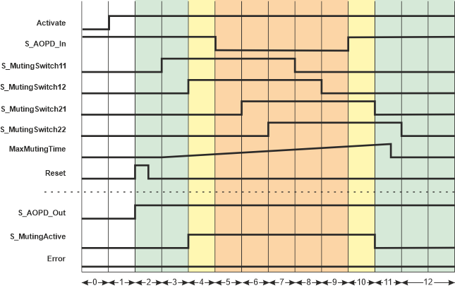
| 0 | The function block is not yet activated (Activate = FALSE). As a result, all outputs are FALSE or SAFEFALSE. |
| 1 | After the function block has been activated by Activate = TRUE, the start-up inhibit is active at first. The S_AOPD_Out output therefore first remains SAFEFALSE. |
| 2 | A positive signal edge at the Reset input resets the start-up inhibit.The S_AOPD_Out output switches to SAFETRUE immediately (normal operation) because the light grid does not detect an object either (input S_AOPD_In = SAFETRUE). |
| 3 | The first muting sensor of the first sequential sensor pair (before the safety-related equipment) at input S_MutingSwitch11 detects an object and switches to SAFETRUE.The time measurement for the overall muting duration starts after this state change at S_MutingSwitch11. The maximum permissible period is specified at MaxMutingTime. |
| 4 | The second muting sensor of the first sequential sensor pair also detects the object (the S_MutingSwitch12 input switches to SAFETRUE).This meets the requirements for a valid muting sequence. The object is identified as permissible and the S_MutingActive output switches to SAFETRUE as a result: Muting is active. |
| 5 | The object reaches the light grid: the S_AOPD_In input switches to SAFEFALSE ("light grid interrupted").As muting is active (S_MutingSwitch11 and S_MutingSwitch12 are still SAFETRUE), the machine may continue to run in the zone of operation: The S_AOPD_Out output remains SAFETRUE. |
| 6 | The object reaches the first muting sensor of the second sequential sensor pair (behind the safety-related equipment): the S_MutingSwitch21 input switches to SAFETRUE.The muting sequence is valid because both muting sensors of the first sensor pair are still SAFETRUE. As a result, outputs S_AOPD_Out and S_MutingActive both remain SAFETRUE. The time measurement for the overall muting duration (timer MaxMutingTime) continues to run. |
| 7 | The second muting sensor of the second sequential sensor pair also detects the object (the S_MutingSwitch22 input switches to SAFETRUE).As SAFETRUE signals are still also present at S_MutingSwitch11 and S_MutingSwitch12 and S_MutingSwitch21, the requirements for a valid muting sequence are met and muting remains active: S_AOPD_Out and S_MutingActive both remain SAFETRUE and timer MaxMutingTime continues to run. |
| 8 | The object leaves the detection area of the first muting sensor before the safety-related equipment: The S_MutingSwitch11 input switches from SAFETRUE to SAFEFALSE.This meets the requirements of a valid muting sequence, i.e., muting remains active. As a result, outputs S_AOPD_Out and S_MutingActive both remain SAFETRUE. The time measurement for the overall muting duration (timer MaxMutingTime) continues to run. |
| 9 | The object leaves the detection area of the second muting sensor before the safety-related equipment: The S_MutingSwitch12 input switches from SAFETRUE to SAFEFALSE.This meets the requirements of a valid muting sequence, i.e., muting remains active. As a result, outputs S_AOPD_Out and S_MutingActive both remain SAFETRUE. The time measurement for the overall muting duration (timer MaxMutingTime) continues to run. |
| 10 | The object has passed the light grid (S_AOPD_In switches back to SAFETRUE). S_MutingSwitch21 and S_MutingSwitch22 are still SAFETRUE.This meets the requirements of a valid muting sequence, i.e., muting remains active. As a result, outputs S_AOPD_Out and S_MutingActive both remain SAFETRUE. The time measurement for the overall muting duration (timer MaxMutingTime) continues to run. |
| 11 | The object moves out of the detection area of the first muting sensor behind the safety-related equipment and toward the zone of operation: The S_MutingSwitch21 input switches to SAFEFALSE.If S_MutingSwitch21 switches to SAFEFALSE within the time set at MaxMutingTime, the muting operation has been completed successfully. S_MutingActive becomes SAFEFALSE and output S_AOPD_Out remains SAFETRUE.As the safety-related equipment has not detected an object and the muting operation has been completed within the specified time set at MaxMutingTime and the state change at S_MutingSwitch21 meets the requirements of a valid muting sequence, no error is reported (Error remains FALSE) and the S_AOPD_Out output remains SAFETRUE ("machine continues to run"). |
| 12 | The S_MutingSwitch22 input also switches to SAFEFALSE and the safety-related equipment does not detect an object. The S_AOPD_Out output remains SAFETRUE as this conforms to a valid muting sequence. The muting operation is, therefore, completed successfully. |
Application example
The graphic below illustrates the connection of four muting sensors (B2, B3, B4, and B5) to the SF_MutingSeq function block. The muting sensors are arranged as two sequential sensor pairs with all sensors aligned identically and installed on the same side of the conveyor.
The material flow direction of the conveyor is from left to right, i.e., the muting sensor pair S_MutingSwitch11/S_MutingSwitch12 is positioned before the safety-related equipment and S_MutingSwitch21/S_MutingSwitch22 is behind the safety-related equipment (as represented in the graphic at the beginning of this topic).
Hinweis
The S_AOPD_Out enable output of the SF_MutingSeq function block is connected to an output terminal of the application via a global I/O variable or via other safety-related functions/function blocks.
The function block outputs OverridePossible, OverrideActive, SafetyDemand, and ResetRequest may be connected to device outputs for signaling purposes. |
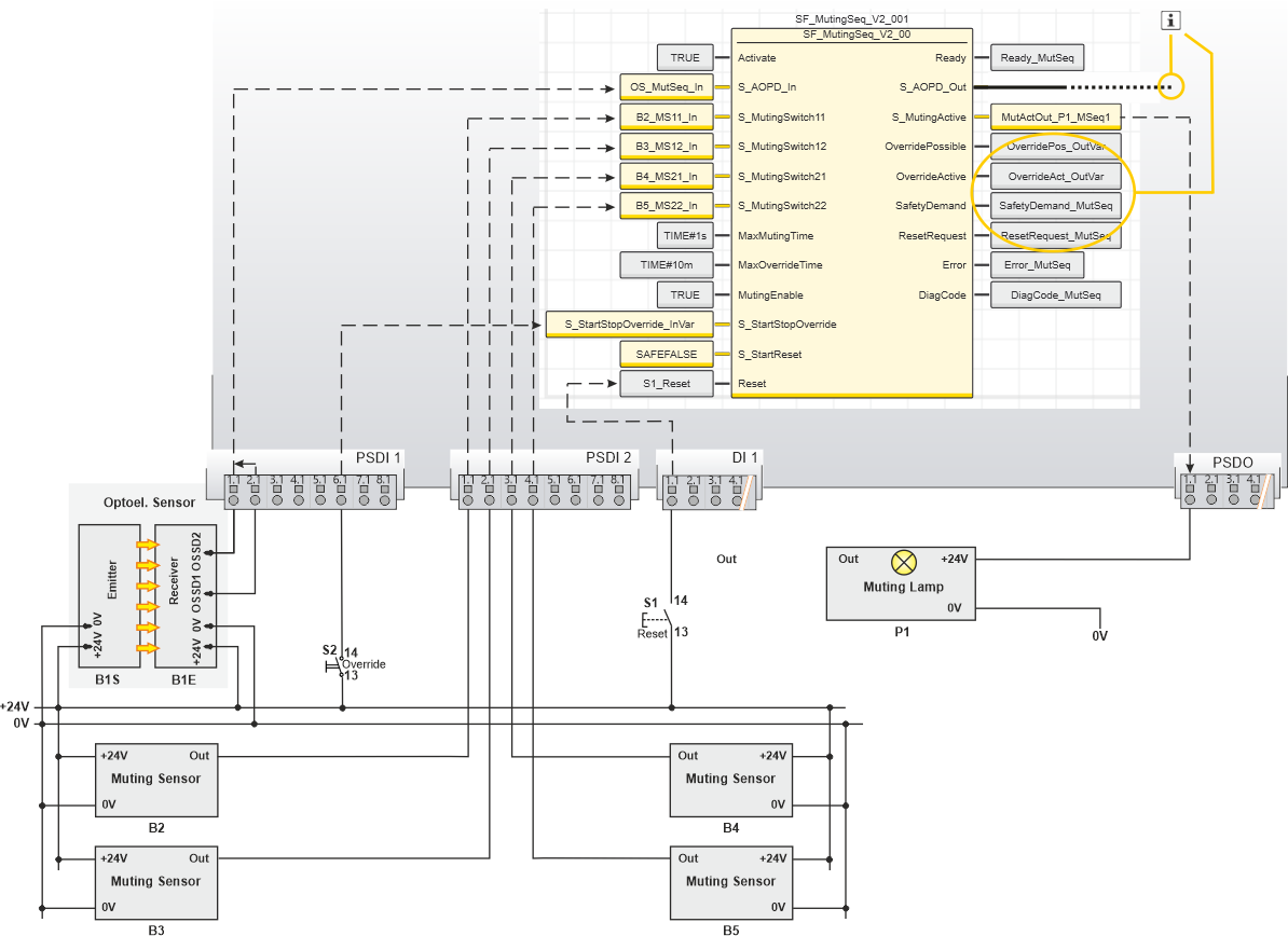
| B1 | Two-channel light grid (B1S = optoelectronic transmitter, B1E = optoelectronic receiver) |
| B2, B3 | Optoelectronic muting sensors (first sequential sensor pair), each single-channel, positioned before the light grid |
| B4, B5 | Optoelectronic muting sensors (second sequential sensor pair), each single-channel, positioned behind the light grid |
| P1 | Muting lamp indicating the active muting process |
| S1 | Reset button (single-channel) to reset function block errors and to remove the start-up inhibit |
| S2 | Override key switch |
 | See note above the illustration. |
Function block instantiation
The IEC 61131-3 standard defines function block instantiation. Instantiation means, a function block is defined once and can be used (instantiated) several times. This applies to all standard and safety-related FBs (local POUs as well as firmware and user library FBs).
Why instantiation?
A function block has an internal memory where it stores its own processing data (local variables). As a consequence, the output values calculated by the FB depend on the internally stored values. The same input values applied to an FB instance do not necessarily deliver the same results in another FB instance.
Therefore, it is necessary to store the internal data of the FB to a separated memory area each time the function block is processed, i.e., for each FB instance. To uniquely identify each FB instance and to clearly separate its memory area, instance names are used. The instance name of a function block has to be declared in the 'Variables' table of the POU where the FB is going to be used.
The following applies:
- Function blocks can be instantiated in other function blocks or in program POUs. Calling FBs in function POUs is not possible.
- Functions are called without instantiation because they do not have an internal memory.
Safety-related and standard (non-safety-related) code is strictly distinguished in PLCnext Engineer. If a Safety PLC is included in your project, the following applies:
- Safety-related FBs can only be instantiated in safety-related POUs but not in standard (non-safety-related) POUs.
- User-defined standard FBs can only be instantiated in standard POUs. They cannot be called in safety-related POUs.
- Particular standard firmware FBs can be instantiated in both safety-related and standard POUs.
Hinweis
When inserting a standard FB into a safety-related SNOLD network, the rules for implicit type conversion (safety-related to standard) apply. |
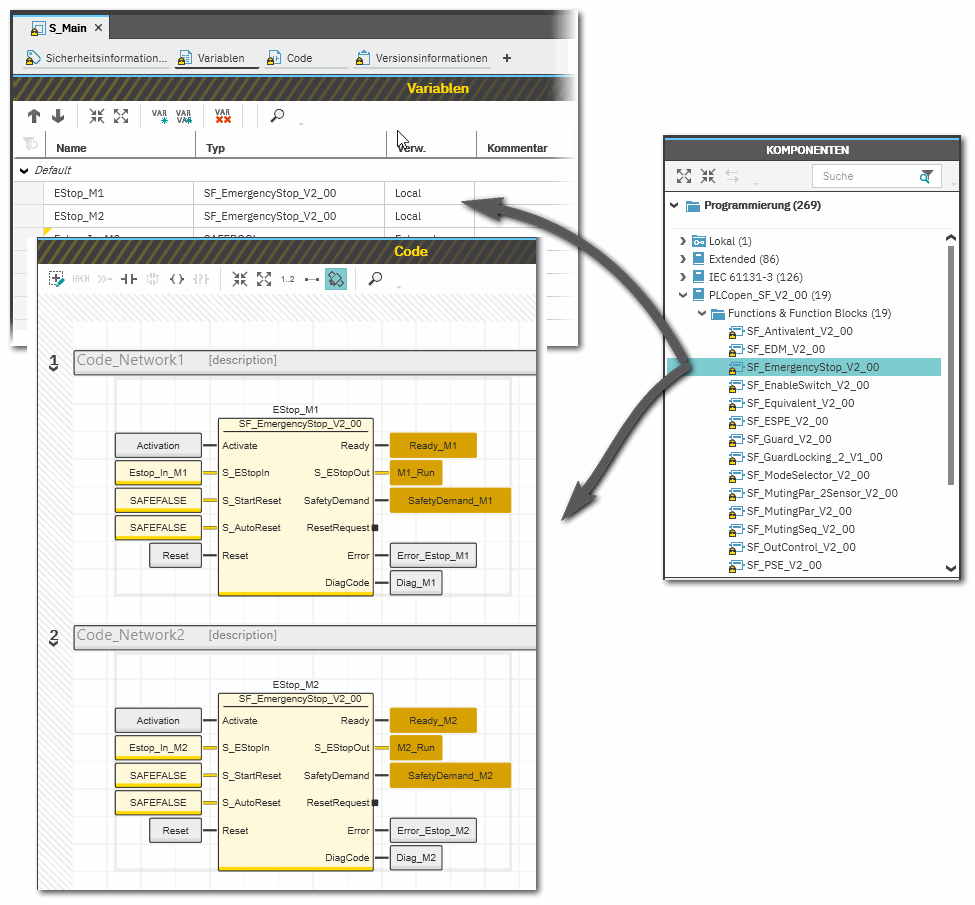
Example for the instantiation of a safety-related PLCopen function block
The safety-related PLCopen function block 'SF_EmergencyStop_V2_00' was inserted into the project via a library. It is then available in the 'Programming' category of the COMPONENTS area. There is a folder with the same name as the library that provides the FBs for insertion into the safety-related code.
The FB is to be called twice in the code of the safety-related program 'S_Main' to evaluate the status of two safety-related emergency stop command devices. For each FB instance, an instance name is declared in the 'Variables' table of the calling program: EStop_M1 and EStop_M2. The FB instances have been inserted into the code worksheet, each instance with different variables connected to its input and output formal parameters.
Additional information is available in the following sections:
|