Additional signal sequence diagrams
Temporary intermediate states are not illustrated in the signal sequence diagram. Only typical input signal combinations are illustrated in this diagram. Other signal combinations are possible.
The most significant areas within the signal sequence diagrams are highlighted in color.
| Weitere Infos
The diagram in the overview for this function block must also be taken into account. |
Person in zone of operation, muting inactive, stop request via safety-related equipment, start-up inhibit active
The signal sequence diagram shown below illustrates what happens if, for example, a person interrupts the light beam of just one of the two muting sensors (see situation (1) in the graphic below) and then moves forward to enter the zone of operation of the protected machine, i.e., the person also interrupts the light beam of the safety-related equipment, thus triggering a stop request (see situation (2) in the graphic).
MS_11: Muting sensor, connected to the S_MutingSwitch11 function block input
MS_12: Muting sensor, connected to the S_MutingSwitch12 function block input
Additional assumptions:
- S_StartReset = SAFEFALSE: Start-up inhibit after the function block has been activated and after the Sicherheitssteuerung has started up.
- MutingEnable = TRUE (constant): No separate enable signal required for the muting operation.
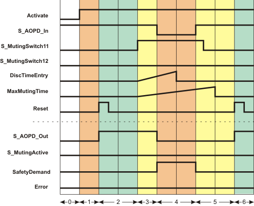
| 0 | The function block is not yet activated (Activate = FALSE). As a result, all outputs are FALSE or SAFEFALSE. |
| 1 | After the function block has been activated by Activate = TRUE, the start-up inhibit is active at first. Therefore, the S_AOPD_Out enable output remains SAFEFALSE. |
| 2 | A positive signal edge at the Reset input resets the start-up inhibit.The S_AOPD_Out output becomes SAFETRUE immediately because
|
| 3 | The person in our example interrupts the light beam of the muting sensor at input S_MutingSwitch11, thus switching the signal to SAFETRUE (situation (1) in the graphic above).This change in state at S_MutingSwitch11 initiates measurement of the discrepancy time DiscTimeEntry (maximum permissible time for the second muting sensor to signal SAFETRUE as well) and the time measurement for the overall muting duration MaxMutingTime. |
| 4 | Before muting can be activated (for which the S_MutingSwitch12 input must also switch to SAFETRUE within DiscTimeEntry), the person also interrupts the light grid of the safety-related equipment (situation (2) in the graphic above), i.e., S_AOPD_In switches to SAFEFALSE.As a result, the S_AOPD_Out enable output switches to SAFEFALSE, as an object (in this case, a person) has been detected inside the zone of operation and muting has not previously been activated. The machine is stopped. The SafetyDemand output switches to TRUE, as the safety chain is now interrupted.When S_AOPD_In switches to SAFEFALSE, the muting operation is canceled. As a result, the function block does not signal an error, although the second muting sensor has not also signaled a SAFETRUE signal at the S_MutingSwitch12 input within the discrepancy time set at DiscTimeEntry. |
| 5 | The person has now left the detection area of the safety-related equipment (i.e., of the light grid). S_AOPD_In switches back to SAFETRUE (temporary situation (1) in the graphic above).Output SafetyDemand switches to FALSE again, as the safety chain is no longer interrupted now.A short time later, the signal of muting sensor S_MutingSwitch11 also switches back to SAFEFALSE, as the person has left the detection area of the muting sensor too.Although the light beams of all sensors are no longer interrupted, the S_AOPD_Out enable output remains SAFEFALSE, as a positive edge is first expected at the Reset input.As the muting operation has already been canceled, it is of no relevance that the MaxMutingTime time measurement elapses without a result. The function block does not detect an error, the Error output remains FALSE. |
| 6 | Pressing the connected reset button applies the expected positive edge to the Reset input. As S_AOPD_In is still SAFETRUE (light beam of the safety-related equipment is not interrupted), the S_AOPD_Out output switches to SAFETRUE ("machine running again"). |
Error-free use of the override function
The signal sequence diagram shown below illustrates a muting operation with override function, using the example of an impermissible object on an assembly conveyor that ends at a zone of operation with a running machine. This is illustrated in the graphic below:
The signal sequence diagram demonstrates an error-free override operation that ends automatically after the object has been removed from the zone of operation.
Additional assumptions:
- S_StartReset = SAFEFALSE: Startup inhibit after the function block has been activated and after the Safety PLC has started up.
- MutingEnable = TRUE (constant): No separate enable signal required for the muting operation.
Steps 0 to 5 correspond to the signal sequence diagram for error-free muting which is shown in the overview topic on this function block.
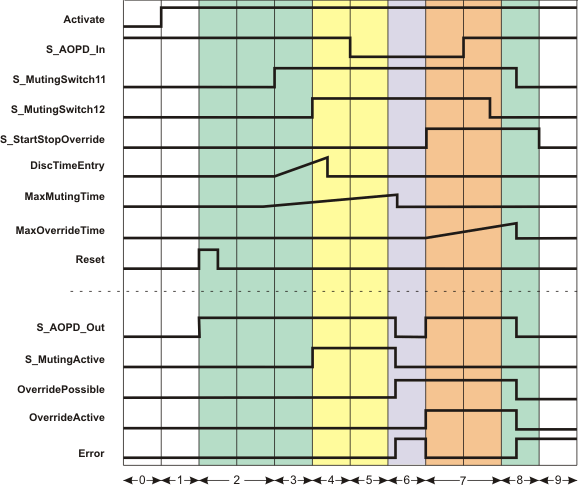
| 0 | The function block is not yet activated (Activate = FALSE). As a result, all outputs are FALSE. |
| 1 | After the function block has been activated by Activate = TRUE, the startup inhibit is active at first. |
| 2 | Positive signal edge at the Reset input resets the startup inhibit.The S_AOPD_Out output switches immediately to SAFETRUE (normal operation) because
|
| 3 | The muting sensor at input S_MutingSwitch11 detects an object and switches to SAFETRUE. This change of state at S_MutingSwitch11 initiates
|
| 4 | The second muting sensor also detects the object (input S_MutingSwitch12 switches to SAFETRUE) within the permissible discrepancy time (DiscTimeEntry).This means that the object is first identified as permissible and the S_MutingActive output switches to SAFETRUE as a result: Muting is active. |
| 5 | The object reaches the light grid: Input S_AOPD_In switches to SAFEFALSE ("light grid interrupted"). As muting is active (S_MutingSwitch11 and S_MutingSwitch12 are still SAFETRUE), the machine may continue to run in the zone of operation: The S_AOPD_Out output remains SAFETRUE. |
| 6 | Even after the timer (set at MaxMutingTime) has elapsed, both muting sensors S_MutingSwitch11 and S_MutingSwitch12 are still SAFETRUE and the light grid is still interrupted (S_AOPD_In = SAFEFALSE).This means a muting error occurs and the Error output switches to TRUE.Muting is immediately deactivated (S_MutingActive output switches to SAFEFALSE) and the machine must not continue to run in the zone of operation. The S_AOPD_Out output switches to SAFEFALSE.The requirements for an override operation are given. The OverridePossible output switches to TRUE. |
| 7 | The operating personnel requests the override operation via a control device (S_StartStopOverride input switches to SAFETRUE). The OverrideActive output switches to TRUE.The override time measuring starts. The maximum permissible duration is specified using the MaxOverrideTime parameter. As a result of the active override operation, the Error output switches to FALSE.The S_AOPD_Out output switches to SAFETRUE, as the override operation is active.Now, the object can be removed from the zone of operation. |
| 8 | The override operation is exited automatically, as the object has been removed (both muting sensors (S_MutingSwitch11 and S_MutingSwitch12 are SAFEFALSE) and the light grid detects no object any more (input S_AOPD_In = SAFETRUE)).As a result, the outputs OverridePossible and OverrideActive switch to FALSE and the override timer (set at MaxOverrideTime) is reset.After the successful override operation, the Error output switches to TRUE again because the previous muting error must first be confirmed by a reset request. The S_AOPD_Out output thus switches to SAFEFALSE. |
| 9 | The operator releases the control device for the override function (S_StartStopOverride input = SAFEFALSE). However, this has no more effect, as the override operation has already been finished automatically. As long as there is no reset request by the operator, the Error output remains TRUE and the S_AOPD_Out output SAFEFALSE. Positive signal edge at the Reset input initiates the reset. |
Errors during the override operation, e.g., override timer has elapsed
The signal sequence diagram shown below illustrates a muting operation with override function, using the example of an object on an assembly conveyor that ends at a zone of operation with a running machine. It demonstrates the behavior when the override timer (MaxOverrideTime input) elapses during the override operation.
This is illustrated in the graphic below.
Additional assumptions:
- S_StartReset = SAFEFALSE: Startup inhibit after the function block has been activated and after the Safety PLC has started up.
- MutingEnable = TRUE (constant): No separate enable signal required for the muting operation.
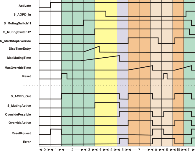
| 0 | The function block is not yet activated (Activate = FALSE). As a result, all outputs are FALSE. |
| 1 | After the function block has been activated by Activate = TRUE, the startup inhibit is active at first. ResetRequest = TRUE indicates that you need a Reset to reset the startup inhibit. |
| 2 | Positive signal edge at the Reset input resets the startup inhibit.The S_AOPD_Out output switches immediately to SAFETRUE (normal operation) because
|
| 3 | The muting sensor at input S_MutingSwitch11 detects an object and switches to SAFETRUE. This change of state at S_MutingSwitch11 initiates
|
| 4 | The second muting sensor also detects the object (input S_MutingSwitch12 switches to SAFETRUE) within the permissible discrepancy time (DiscTimeEntry input).This means that the object is identified as permissible and the S_MutingActive output switches to SAFETRUE as a result: Muting is active. |
| 5 | The object reaches the light grid: Input S_AOPD_In switches to SAFEFALSE ("light grid interrupted"). As muting is active (S_MutingSwitch11 and S_MutingSwitch12 are still SAFETRUE), the machine may continue to run in the zone of operation: The S_AOPD_Out output remains SAFETRUE. |
| 6 | Even after the timer (MaxMutingTime input) has elapsed, both muting sensors S_MutingSwitch11 and S_MutingSwitch12 are still SAFETRUE and the light grid is still interrupted (S_AOPD_In = SAFEFALSE).This means a muting error occurs and the Error output switches to TRUE.Muting is immediately deactivated (S_MutingActive output switches to SAFEFALSE) and the machine must not continue to run in the zone of operation. The S_AOPD_Out output switches to SAFEFALSE.The requirements for an override operation are given. The OverridePossible output switches to TRUE. |
| 7 | The operating personnel starts the override operation via a control device (S_StartStopOverride input switches to SAFETRUE). The OverrideActive output switches to TRUE.The override time measuring starts. The maximum permissible duration is specified at the MaxOverrideTime input. As a result of the active override operation, the Error output switches to FALSE.The S_AOPD_Out output switches to SAFETRUE, as the override operation is active.Now, the object can be removed from the zone of operation. |
| 8 | An override error has occured because the override timer (MaxOverrideTime input) has elapsed before the object could be removed completely from the zone of operation.As a result, the S_AOPD_Out output switches to SAFEFALSE and Error to TRUE. OverridePossible and OverrideActive switch to FALSE. A reset is required because of the override error and this is signaled at output ResetRequest (ResetRequest = TRUE). The operator releases the key switch (input S_StartStopOverride = SAFEFALSE), but there is no further effect. |
| 9 | Positive signal edge at the Reset input initiates the reset.With the reset the requirements for the override function are given again because one of the muting sensors still detects an object (S_MutingSwitch12 = SAFETRUE) and the error state still remains (Error = TRUE). The OverridePossible output thus switches to TRUE. |
| 10 | Now, the operator can start an override operation again (input S_StartStopOverride = SAFETRUE). The override timer (MaxOverrideTime input) starts again.The output OverrideActive switches to TRUE and S_AOPD_Out switches to SAFETRUE, the Error output switches to FALSE again. The removal of the object from the zone of operation can be continued. |
| 11 | With the switch of S_MutingSwitch11 to SAFEFALSE the requirements for the automatic exit of the override operation are met:
|