LOGIC ANALYZER: Monitoring the Application
This topic and its subtopics provide information about the following:Important notes on the LOGIC ANALYZER
Observe the following notes when using the LOGIC ANALYZER:
- The LOGIC ANALYZER may not be available for all controller types.
- The safety-related application is currently not supported by the LOGIC ANALYZER. Therefore, this topic only applies to the standard (non-safety-related) controller. The debugging tools available for the Safety PLC are described in the help chapter "Safety PLC Commissioning: From Compiling to Debugging
 ‣ Safety PLC Commissioning: From Compiling to Debugging
×‣ Connecting vs. Monitoring Mode vs. Debug Mode
×‣ Safety Cockpit: Controlling the Safety Application
×‣ Safety PLC Diagnostics out of the Safety Cockpit
×‣ Monitoring/Debugging the Safety PLC
×‣ Monitoring Mode: Displaying Online Values
×‣ Debugging Safety-Related Code: Forcing/Overwriting
×‣ WATCHES: Monitoring/Debugging the Safety-Related Application
×‣ Safety PLC Simulation
×". - Besides the LOGIC ANALYZER, the Data Logger is available on PLCnext Technology controller types. This tool embedded into the controller firmware also allows the recording of data without having PLCnext Engineer connected during recording.
- The update rate of online values depends on the set 'Polling interval' which is specified in the 'Options' dialog. The higher the interval value, the less data is transferred in the background between PLCnext Engineer and the controller, i.e., the longer the time until the next online value update in online worksheets, the WATCHES window, and the LOGIC ANALYZER.
Therefore set the interval value as short as the Internet connection allows. See topic "TCP Communication Connection". - The LOGIC ANALYZER configuration (list of subscribed variables, view settings, trigger settings etc.) is saved within the current PLCnext Engineer project and available when you load the project again.
General information
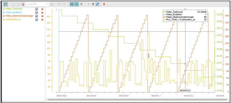
The LOGIC ANALYZER is a tool for recording variable values on the running controller and visualizing them graphically as curves with adjustable scales on both the x-axis (time) and y-axis (variable value).
Up to 16 variables can be recorded at the same time.
The LOGIC ANALYZER supports variables and ports from IEC 61131-3 POUs as well as ports from (external) non-IEC 61131-3 programs.
| Note
In the following description, the term "variables" also includes ports. |
User-defined data types such as ARRAYs and STRUCTs can also be inserted into the LOGIC ANALYZER. On insertion, a selection window appears where you can decide which members should be inserted an subscribed (see Step 1).
 Example: Visualized curves of recorded values in the LOGIC ANALYZER
 | The LOGIC ANALYZER window is located in the Cross Function Area at the lower screen border. You can hide/show the window by clicking the LOGIC ANALYZER window button on the Cross Function Area toolbar. |
While the controller is running and debug mode is active in PLCnext Engineer (variable/port values are visible in code worksheets and variables tables, or data/port lists), you can add variables/ports to be monitored to the LOGIC ANALYZER subscription list and then start the recording session. The LOGIC ANALYZER acts as a subscriber of these online variables in the controller runtime process. Values are recorded and buffered on the controller, and transferred to PLCnext Engineer.
The LOGIC ANALYZER is able to record and display numeric values, Boolean values (which are internally converted to the numeric values 0 and 1) as well as bit values (converted to numeric representation). Additionally, the LOGIC ANALYZER allows to export recorded data. Exported data can be imported again and displayed as curves, for a later review.
The LOGIC ANALYZER configuration is saved within the current PLCnext Engineer project and available when you load the project again. The configuration includes the following:
- List of subscribed variables
- Default sample rate
- View settings
- Trigger settings
| Note
Any time you modify the LOGIC ANALYZER configuration, the PLCnext Engineer project will change. |
Recording modes
The LOGIC ANALYZER supports two recording session modes. In both modes, the session has to be started manually by clicking the respective button on the LOGIC ANALYZER toolbar.
 | Manual session
Recording of the variables added to the subscription list is started immediately. No trigger conditions have to be defined. Recorded variables values are continuously loaded into the LOGIC ANALYZER window and visualized there.Recording is continued until manually stopped with the toolbar button  . . |
 | Triggered session
Recording of the variables added to the subscription list is only started if the conditions defined as trigger event in the 'Trigger Configuration' dialog box are met. At the time the trigger event occurs, subscribed data recorded before the trigger event is loaded into the LOGIC ANALYZER window and visualized. Then, the recording is continued continuously. The triggered session is automatically finished when the defined number of cycles after the trigger event is reached. While recording, the session can be stopped at any time by clicking the toolbar button .The number of recording cycles before and after the trigger event have to be defined by clicking the following icon right of the task selection drop-down list.
 |