Alarming
PLCnext Engineer allows you to configure an alarming system. The alarming system provides a tool for notifying the operator about alarms originated in the alarm source (for example, protocol, application program, PLCnext component).
Alarms are used to display warning messages informing the operator about faulty or abnormal conditions and deviations, or status changes in the alarm source that could cause problems and require the response of the operator. Whenever the value of, for example a variable, exceeds a threshold value or a pattern of a digital signal matches a preconfigured pattern, an alarm becomes active and a message is displayed during process operation to notify the operator of a problem.
The alarm configuration is stored in an alarm array. The alarm array is filled with the alarm information queried from the alarm source (for example, protocol, application program, PLCnext component).
The alarms configured in PLCnext Engineer can be visualized to the operator via user-defined HMI elements. To get access to the elements of the alarm array, i.e. the global list of alarms, their properties and values, the HMI symbol list in PLCnext Engineer provides a specific data source type, named 'AlarmView'. Using this data source type, the operator can interact with the alarming system (watch, acknowledge, confirm etc. alarms).
| Further Info
For details on the interaction between the alarming system configured in the application program and the HMI visualization, see the topic "HMI Alarming". |
This topic contains the following sections:
- 'Alarms' editor
- Alarm properties
- Editing and organizing alarm definitions
- Importing/Exporting alarms
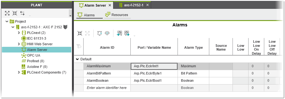
'Alarms' editor
The definition of the alarms, the selection of the signal to be monitored and the configuration of the basic properties of the alarms are configured in the 'Alarm Server | Alarms' editor. You open this editor via the 'Alarm Server' node in the PLANT.
Alarm properties
For each alarm the following properties can be defined in the 'Alarms' editor:
| Property | Description |
|---|---|
| Alarm ID | Unique name of the alarm within the controller used to identify the alarm (must not contain blanks or special characters). |
| Port / Variable Name | Mandatory scalar data value that is monitored in order to detect an alarm condition (value in the format <PLCnext component name>/<element name>). The combobox contains all possible data values.Examples:
|
| Alarm Type | Alarm type of the alarm. Depending on the selected alarm type, various alarm properties are read-only.You can select between the following alarm types:
|
| Source Name | Name of the module that is the source of the alarm (for example, protocol, PLC program, PLCnext component). |
| LowLow | The alarm will be triggered when the value of the monitored data value (literal or port) is lower than or equal to the 'LowLow' limit. The limit value must match the data type of the monitored data value. |
| LowLow On Delay | On delay time, in seconds, valid for the 'LowLow' alarm.If set then the value of the monitored data value (literal or port) has to be above the alarm threshold ('LowLow' limit) for the duration of 'On Delay' before the alarm is triggered.You can use the on delay time to avoid unnecessary notification of the operator when the monitored value temporarily exceeds the alarm limit. |
| LowLow Off Delay | Off delay time, in seconds, valid for the 'LowLow' alarm.If set then the alarm is kept on (remains in the active state) even the value of the monitored data value (literal or port) falls below the alarm threshold ('LowLow' limit). The alarm will not be reset until the monitored data value is lower than the alarm threshold for the duration of 'Off Delay'. |
| Low | The alarm will be triggered when the value of the monitored data value (literal or port) is lower than or equal to the 'Low' limit. The limit value must match the data type of the monitored data value. |
| Low On Delay | On delay time, in seconds, valid for the 'Low' alarm.See the description of the 'LowLow On Delay' property above. |
| Low Off Delay | Off delay time, in seconds, valid for the 'Low' alarm.See the description of the 'LowLow Off Delay' property above. |
| High | The alarm will be triggered when the value of the monitored data value (literal or port) is higher than or equal to the 'High' limit. The limit value must match the data type of the monitored data value. |
| High On Delay | On delay, in seconds, valid for the 'High' alarm.See the description of the 'LowLow On Delay' property above. |
| High Off Delay | Off delay time, in seconds, valid for the 'High' alarm.See the description of the 'LowLow Off Delay' property above. |
| HighHigh | The alarm will be triggered when the value of the monitored data value (literal or port) is higher than or equal to the 'HighHigh' limit. The limit value must match the data type of the monitored data value. |
| HighHigh On Delay | On delay valid for the 'HighHigh' alarm.See the description of the 'Low On Delay' property above. |
| HighHigh Off Delay | Off delay valid for the 'HighHigh' alarm.See the description of the 'Low Off Delay' property above. |
| Value | Mandatory value for the alarm types 'Bit Pattern' and 'Boolean' (see above).For the 'Boolean' alarm type, enter a boolean enumeration value (allowed values: TRUE, BOOL#1, BOOL#TRUE, FALSE, BOOL#0, BOOL#FALSE). The 'Port / Variable Name' value is compared to the entered 'Value' in order to trigger the alarm. When the value of the monitored digital variable matches the value, the alarm is triggered.For the 'Bit Pattern' alarm type, enter a bit mask that is used for testing. The bit mask is compared with the pattern of the monitored digital signal. When the comparison between the two bit patterns is TRUE, the alarm is triggered. |
| Value On Delay | On delay time, in seconds, valid for the 'Out Of Range' alarm (value alarm).See the description of the 'LowLow On Delay' property above. |
| Value Off Delay | Off delay time, in seconds, valid for the 'Out Of Range' alarm (value alarm).See the description of the 'LowLow Off Delay' property above. |
| Priority | Alarm priority that informs the operator of the urgency of the alarm. 1 represents the lowest alarm priority (informative), 1000 the highest alarm priority (fatal error).Typically, a severity of 1 would indicate an event which is informational in nature, while a value of 1000 would indicate an event of catastrophic nature, which could potentially result in loss of life. |
| Message | Text description of the alarm event that will be shown to the operator in the HMI application when the alarm is active. The description can be localized (translated into other languages) using the 'Alarm Server | Resources' editor.See topic "Localization of Alarm Messages and Descriptions" for details. |
| Description | Short description of the alarm condition that will be shown to the operator in the HMI application when the alarm is active. The description can be localized (translated into other languages) using the 'Alarm Server | Resources' editor.See topic "Localization of Alarm Messages and Descriptions" for details. |
| Access Rights | Configures the action(s) that the operator must take when an alarm is active.The following actions can be configured:
|
| Suppress Condition Variable Name | Only available if the 'Suppression Allowed' action is activated (see the description above).Condition based on a process value (variable or port) of type Boolean that will suppress the alarm so that it is not shown to the operator.The alarm continues to function as before. Only the state Suppressed is additionally set, so that the client does not display this alarm or displays it differently. |
| Enabled | If checked, the evaluation of the alarm will be processed (checked by default), i.e., the 'Port / Variable Name' value is monitored for an abnormal condition. When unchecked the alarm is excluded in the alarm configuration file. |
Editing and organizing alarm definitions
| Note
To create a valid alarm configuration, a program instance of type 'AlarmProgram' (available by default) must be assigned to a task in the 'Tasks and Events' editor. |
Add an alarm
- Assign a program instance of type 'AlarmProgram' to a task in the 'Tasks and Events' editor.
- In the 'Alarms' editor, enter the alarm ID in an empty 'Alarm ID' cell and press <Enter>. Alternatively, click the toolbar button
 .
. - In the 'Port / Variable' column, select the data value to be monitored (value in the format <PLCnext component name>/<element name>; e.g., Arp.Plc.Eclr/SampleIntegerVariable).
- Select the 'Alarm Type' in the 'Alarm Type' column. The 'Alarm Type' must match the data type of the 'Port / Variable'. For example, a 'Boolean' alarm type expects a 'Port / Variable' of type BOOL. Depending on the selected type, different alarm properties will be enabled/disabled.(When your alarm definition has an error, an error message appears in the 'Error List' in the MESSAGES window.)
- Configure the alarm properties. (Regard the 'Error List' in the MESSAGES window for any invalid configurations.)
Organize alarms
You can use alarm groups to organize the configured alarms. To create an alarm group, click the  button on the toolbar.
| Further Info
Alarm messages and descriptions can be localized, i.e., translated into other languages allowing you to create multilingual alarm messages. For details on this procedure, see the topic "Localization of Alarm Messages and Descriptions". |
Importing/Exporting alarms
To export the alarm definitions to a .csv file, click the  button on the toolbar.
| Note
If you edit the exported csv file with an external tool, you must make sure that the editor used does not change the column separators (semicolons) or the file encoding. For example, MS Excel may be set to modify csv files so that they cannot be reimported. |
To import alarm definitions from a .csv file, click the  button on the toolbar. In the file open dialog, select the .csv file you want to import and click 'Open'.