Configuring the Modbus/TCP Local Server
As of firmware version 2026.0, the PLCnext Technology controller firmware is enhanced with an integrated Modbus/TCP server (Modbus/TCP local Server). Refer to the PLCnext Info Center regarding Modbus/TCP support for specific controllers.
| Note
The Modbus local server must be enabled on the WBM page 'System Services' of the controller to configure Modbus communication. |
| Further Info
See the topic "Modbus/TCP Configuration" for general information on Modbus/TCP. |
This topic contains the following sections:
- Configure the local server settings
- Configure the Modbus/TCP registers
- Edit the data list of the local server
- Edit the port list of the local server
Configure the local server settings
| Note
Modbus/TCP client and server devices are provided in a separate library named Modbus. In order to be able to use the Modbus/TCP devices in the project, the 'Modbus' library has to be integrated in the COMPONENTS area in the project (see the topic "Adding libraries" for details). |
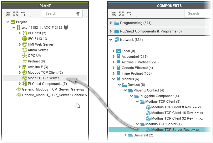
The Modbus/TCP local server appears under the Modbus TCP Server node in the PLANT after you have added the Modbus TCP server device via drag & drop from the COMPONENTS area.
To configure the settings of the Modbus/TCP local server and the connection to the Modbus/TCP client, open the 'Settings' editor of the device by double-clicking the device node in the PLANT. In the 'Modbus TCP server' category in the 'Settings' editor, configure the following parameters:
| Parameter | Description |
|---|---|
| 'Swap bytes' | Defines the byte order (little endian or big endian) used to parse the register information. By default, big endian is used (parameter set to 'No'). To use little endian ordering, set the parameter to 'Yes'.Default value: 'No' |
| 'Port' | TCP/IP port used by the server, i.e., port on which the Modbus/TCP server listens.Default value: 502 for Modbus/TCP |
| 'Watchdog trigger time' | Trigger time in ms for the process data item watchdog. The watchdog is disabled at the trigger time of 0 ms.Default value: 0 ms |
| 'Watchdog register' | A read or write access to the selected register triggers the watchdog (default: 0).The specified register address is not simultaneously defined as a holding register in the 'Registers' editor. |
| 'Watchdog hold inputs' | Specifies the behavior of the watchdog holding registers (output registers) in case of a process data item watchdog (watchdog is only activated with a 'Watchdog trigger time' greater than 0 ms). Possible values:
|
| 'I/O Update time' | Update cycle time in ms for reading the Modbus telegrams of the client from the Ethernet stack.Default value: 500 ms (value range: 10 to 600000 ms) |
Configure the Modbus/TCP registers
The Modbus/TCP registers that the local server provides for the communication with the client are configured using the server's 'Registers' editor (editor of the server's editor group). In the editor, the register type (holding registers, input registers) can be specified for the server, which the client can access via various function codes. (The client decides which function codes should be used to exchange data between client and server.)
Proceed as follows:
- In the 'Function Code' column, select the function code category to be provided by the server to the client and press <Enter>.
- In the 'Name' column, enter a register name (description of the register) and press <Enter>.Depending on the selected function code, an access type (default names: 'input' and/or 'output') is added (a new table row is added after the selected function code for each access type). In the 'Data List' editor of the server the process data item with the name built from the register name and the access type is automatically created. The same applies to the port name in the 'GDS Port List' of the server.
- Optional: Edit the access type name.
- Define the following parameters for the register:
Parameter Description 'Data Direction' Read-only parameter. Indicates whether it is input data or output data. The possible values depend on the selected function code.Possible values: INPUT (read function code), OUTPUT (write function code) 'Data Type' Data type of the Modbus/TCP register data. Specifies how the data is represented in the server.Possible value: WORD 'Address' Starting address of the data in dec format to be accessed in the server. The address is the address of the first coil/register to start the write/read operation. 'Quantity' Number of coils/registers (bits/words) to be read/written for the register.
 Example
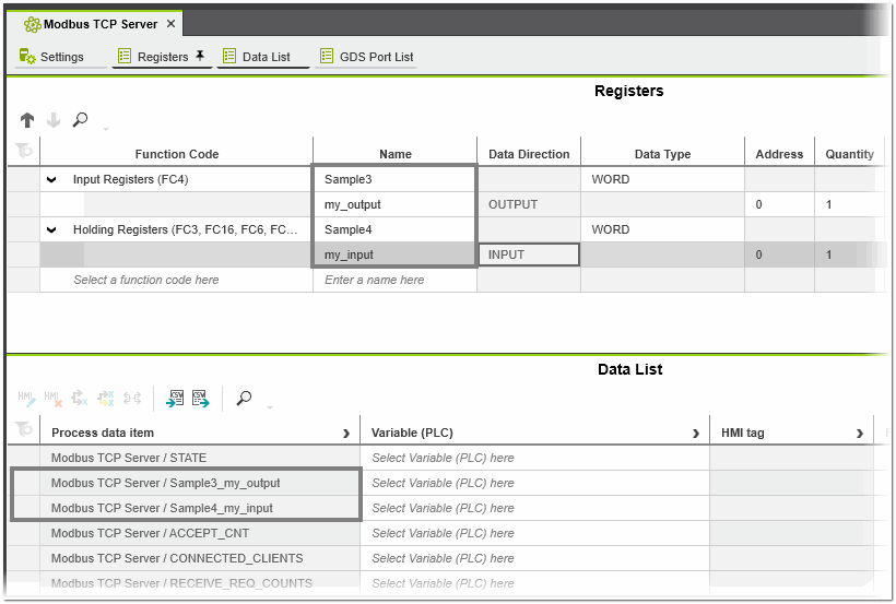
Edit the data list of the local server
The 'Data List' editor of the server contains the process data items created from the register names and access types in the 'Registers' editor (see above). In addition, the following diagnostic data is provided as process data items for the configured server (filled with information from the firmware).
| Parameter | Description |
|---|---|
| STATE | Diagnostic status bits |
| ACCEPT_CNT | Number of connections established so far |
| CONNETED_CLIENTS | Number of currently connected clients |
| RECEIVE_REQ_COUNTS | Number of valid requests received. |
| EXCEPTION_CNT | Number of exceptions sent |
| EXCEPTION_CODE | The last exception code sent |
| EXCEPTION_FC | Function code of the last exception that caused an error |
| EXCEPTION_REG_ADDR | Modbus register address of the exception |
| ERR_CODE | Last connection error code |
| CONTROL_DIAG_STATISTIC | Used to reset the diagnostic data and close the connection to all clients. List of control data:
|
| Further Info
For more information on editing data items, see the topic "Data Lists". |
Edit the port list of the local server
Use the 'GDS Port List' editor to map the IN and OUT ports of the local server to each other. The editor contains the IN and OUT ports created from the register names and access types in the 'Registers' editor (see above). In addition, the diagnostic data listed in the previous section is provided as IN and OUT ports for the configured server (filled with information from the firmware).