Redundancy MRP
The 'Redundancy MRP' view shows the MRP (Media Redundancy Protocol) ring topology. Devices running the MRP are represented in the physical topology by specific symbols (see below). The role of the device in the MRP ring is shown in the device tooltip. PLCnext Engineer detects which device is the MRM (Media Redundancy Manager) and which devices are MRCs (Media Redundancy Clients). Blocked ports are represented by specific port symbols. The port state and also the port role are shown in the port tooltip. Non-MRP devices are greyed out in the topology.
Symbols and ports specific to the 'Redundancy MRP' view
| Note
You can switch the display of the devices between two modes: standard and individual. In standard mode, the device symbol as listed in the following table are used for the representation of the devices. In individual mode, the device icon stored in the device description file of the device (e.g., FDCML, GSDML, etc.) is shown as device symbol. To switch the display, click the  button in the toolbar of the 'Physical Topology' editor (see also the topic "Enabling/Disabling Display of Device Graphics" for further details). button in the toolbar of the 'Physical Topology' editor (see also the topic "Enabling/Disabling Display of Device Graphics" for further details). |
| Symbol | Device / Port |
|---|---|
 | MRM (Media Redundancy Manager)The MRM functions as manager in the MRP ring. It monitors and controls the ring topology. In the MRP ring, there is one node serving as MRM. All other nodes in the ring are MRCs. |
 | MRC (Media Redundancy Client)The MRC is a member node of the MRP ring. It forwards the received frames only to the opposite ring ports. |
 | Blocked portA blocked port drops all received data frames except the control frames. |
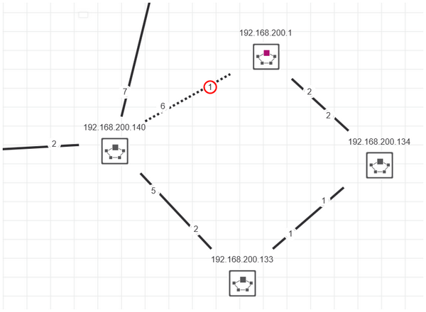
Example of an MRP topology