Physical Topology Editor
The 'Physical Topology' editor displays a graphical view of your network. Using specific scan options configured in your project, PLCnext Engineer scans your network and creates a physical topology visualizing the topological relationship between the Ethernet devices (hereafter referred to as devices) within your network. The editor is opened by double-clicking the 'Project' node in the PLANT and activating the 'Physical Topology' editor in the 'Project' editor group.
 Physical topology example
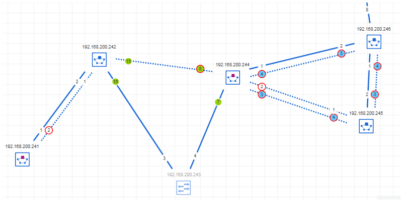
The 'Physical Topology' editor shows the following elements:
- Discovered devicesThe editor shows devices either by specific standard symbols which describe the type of the device or by the device icons stored in the device description file (e.g., FDCML, GSDML, etc.) of a device. The IP address of the device is displayed as device name above the symbol, if available. If enabled in the 'Options' dialog, the device label is shown in the symbol.The color of the device symbol indicates whether the element is only
- an online device, i.e., discovered by a network scan but not yet contained in the PLCnext Engineer project).
- an online device with assigned project device.
- a project device, i.e., added to the project but not assigned to an online device or online device was not found during the last scan.
- Connections between network devicesConnections are represented by a line between the network devices. The line style indicates the type of the connection (for example, a wireless connection is represented by a dashed line).
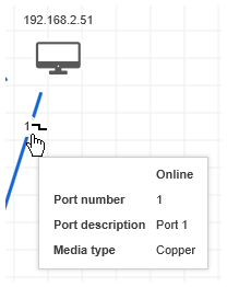
- Port informationThe ports used for the network connection are shown at the line ends. If the port number cannot be identified, a question mark will appear instead of the port number.Depending on the selected topology representation (see below), the ports are indicated by specific symbols. For example, a blocked port in MRP (Media Redundancy Protocol) view is displayed by a red-bordered circle.
- Unconnected devicesDevices that do not have any connections to other network devices are shown in the 'Unconnected devices' subeditor. Unconnected means, no physical connection to other network devices could be found in your network. Unconnected devices are represented by the same symbols than the devices in the 'Physical Topology' editor.The devices are placed automatically in the subeditor and cannot be moved inside the editor. With drag and drop, you can move unconnected devices between the 'Unconnected devices' subeditor and the 'Physical Topology' editor. Just press the <Shift> key as you drag the device between the two editors.
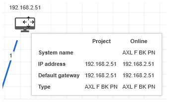
- Tooltips for devices, connections, and portsThe tooltips provide information on the network object. Depending on the topology representation and object selected, different information is displayed. If, for example, an online device has an assigned project device, the tooltip provides the device properties such as the system name, IP address, etc. for the online and project device.
- Online device parameter valuesFor diagnosis purposes, online parameter values of the network devices can be retrieved and displayed. The parameters and their values are shown in the 'Online info snapshots' subeditor. Parameter value snapshots captured from selected devices at different times allows you to check the history of the device's parameter values.
Click the following links to get further information on the 'Physical Topology' editor: