Assigning IP Addresses to the Controller Pair
This topic provides the following information:
Physical and virtual IP addresses of the controllers in the redundant control system
Each LAN port of the controllers in the redundant control system has its own unique physical IP address that is used to directly access the port and to communicate in the Ethernet network. In addition to this physical IP address, a third virtual IP address (system IP address) is assigned to the pair of LAN ports in the PRIMARY and BACKUP controller. The virtual IP address is always bound to the PRIMARY controller and only active in the PRIMARY controller at a time. The address is used for the communication between PRIMARY controller and PLCnext Engineer (for online and debug functions) and by the BACKUP controller to access the PRIMARY controller (i.e., to communicate with the controller that controls the process). This means, all data sent to the virtual IP address is always handled by the PRIMARY controller.
The virtual IP address must be the same for each LAN port pair of the two controllers (for example, LAN port 1 of controller 1 and LAN port 1 of controller 2).
If the PRIMARY (active) controller fails, the virtual IP address is switched over to the BACKUP controller. This ensures that the BACKUP controller takes over the role of the PRIMARY controller (i.e., it controls the process) and maintains the communication with PLCnext Engineer.
The address assignment for the LAN ports and specifying the IP addresses of the controllers can be done in PLCnext Engineer (see below) or directly at the controller.
Requirements for the IP address assignment
There are the following requirements for the assignment of the IP addresses for the LAN ports of the controllers in a redundant control system:
- The physical IP addresses of each LAN port pair of the FIRST and SECOND controller are automatically derived from the virtual address setting as follows: Physical address of FIRST controller = virtual IP address + 1 Physical address of SECOND controller = virtual IP address + 2
- The physical IP addresses of each LAN port pair of the two controllers (for example, LAN port 1 of controller 1 and LAN port 1 of controller 2) must be in the same subnetwork.
- The physical IP addresses of the different LAN port pairs of the two controllers must be in different subnetworks.
- At least, you must assign a valid IP address to the Profinet port of the controller to support Profinet System Redundancy. For the RFC 4072R controller, this is the LAN1 port as the Profinet controller functionality is available at this interface.
Configuring the IP addresses for the LAN ports for the controller pair
The configuration of the IP addresses for the LAN ports of the controllers is done using the 'Settings' editor of the controller node.
Proceed as follows:
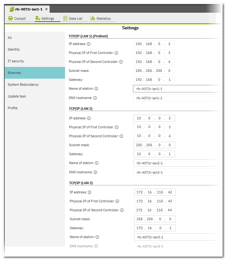
- In the PLANT, double-click the controller node to open its properties. Open the 'Settings' editor and select the 'Ethernet' category.The category shows the IP configuration for the redundant control system. There is a separate parameter group labeled with 'TCP/IP...' for every configurable LAN port of the two controllers.
- Enter the IP address in the 'IP address' field. When entered, the physical IP addresses of the FIRST and SECOND controller are automatically derived from the entered address (as described above) and entered in the corresponding fields (the values cannot be edited).
For the RFC 4072R controller, this is the LAN1 port as the Profinet controller functionality is available at this interface.Note
At least, you must assign a valid IP address to the Profinet port of the controller to support Profinet System Redundancy.Note
The 'IP address' is the virtual IP address assigned to the pair of LAN ports in the PRIMARY and BACKUP controller (see above). - Enter the other network parameters for the LAN ports (observe the requirements above).
Once you have completed the configuration, you can connect to the controller for the purpose of project download, debugging, gathering information on the redundant control system, etc. via the controller Cockpit (see also the topic "Disabling/Enabling Synchronization of Variables/Port Values").
 Example for an IP configuration of a redundant control system