PLCnext Technology System Variables
The following system variables are available for controllers of the PLCnext Technology. The variables are shown in the Data List editor of the controller node in the PLANT.
Further Info
For an up-to-date list and description of the provided system variables, please refer to the PLCnext documentation. |
This topic contains the following sections:
Note
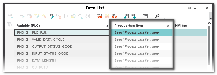
Invisible assignments of system variables: From controller firmware version 2025.6, the assignments between system variables and process data items (PDIs) are no longer visible in the Data List. These PDI connections are provided by firmware or fieldbus components. Although the assignments are no longer visible, the connections between variables and PDIs still exist after the controller is started. The connections are created by the firmware. The function therefore remains guaranteed, even if the assignments are no longer visible. No selection can be made in the 'Process data item' column of the Data List despite the display 'Select Process data item here...'.
Example: Data List display after FW 2025.6:
 |
Controller-related System Variables
DEVICE_STATE (device state)
- The system variable DEVICE_STATE is organized as a data structure.
- You can use the DEVICE_STATE system variable to retrieve various information
about the device status of the CPU.
 Click here for a description of the variable
| System variable | Type | Description |
| DEVICE_STATE | DEVICE_STATE_X152_TYPE | Data structure |
| 1 | BOARD_TEMPERATURE | SINT | Temperature inside the housing (in °C). |
| 1 | reserved1 | BOOL | Reserved |
| 1 | RAMDISK_USAGE | USINT | Current usage of the RAM memory. |
| 1 | CPU_LOAD_ALL_CORES | USINT | Average current utilization of all processor cores (in %). |
| 1 | CPU_LOAD_PER_CORE | CPU_LOAD_PER_CORE_ARRAY | Information on the utilization of
each processor core. |
| 1 | 1 | [1] | USINT | Current utilization of processor core 1 (in %). |
| 1 | 1 | [2] | USINT | Current utilization of processor core 2 (in %). |
| 1 | 1 | [3] | USINT | Current utilization of processor core 3 (in %). |
RTC (system time)
- The system variable RTC is organized as a data structure.
- You can use the RTC system variable to retrieve information about the system time of
the device-internal real-time clock.
Click here for a description of the variable
| System variable | Type | Description |
| RTC | RTC_TYPE | Data structure |
| 1 | HOURS | USINT | System time (hours) |
| 1 | MINUTES | USINT | System time (minutes) |
| 1 | SECONDS | USINT | System time (seconds) |
| 1 | DAY | USINT | System time (day) |
| 1 | MONTH | USINT | System time (month) |
| 1 | YEAR | UINT | System time (year) |
USER_PARTITION (partition)
- The system variable USER_PARTITION is organized as a data structure.
- You can use the USER_PARTITION system variable to retrieve various information
and memory statistics on the user partition (overlay file system).
- The memory is organized in blocks.
- A block has a constant, fixed size and a file always uses one or more blocks.
- A certain number of blocks are reserved in the Linux system for the root user. These
reserved blocks are only available for the root user and ensure his ability to act even
if the memory is occupied (e.g., for log outputs).
Click here for a description of the variable
| System variable | Type | Description |
| USER_PARTITION | PARTITION_INFO | Data structure |
| 1 | MEM_TOTAL | ULINT | Total memory of the partition in bytes (including reserved
blocks). |
| 1 | MEM_FREE | ULINT | Free, available memory in bytes (without reserved blocks). |
| 1 | MEM_USED | ULINT | Used memory in bytes (including reserved blocks). |
| 1 | MEM_HANDLING | ULINT | Used memory in % (without reserved blocks). |
Project-related System Variables
You can use the PLC_CRC_PRJ system variable to retrieve the checksum of the standard (non-safety-related) project part which was calculated last. You can use this checksum to find out whether the project has been modified compared to older project versions.
| System variable | Type | Description |
| PLC_CRC_PRJ | ULINT | CRC of the non-safety-related project. |
IP/TLS Sockets-related System Variables
The library 'Extended Functions & Function Blocks' provides TCP_SOCKET and UDP_SOCKET function blocks to open and close the IP sockets that are used for IP communication via Transmission Control Protocol (TCP) or via User Datagram Protocol (UDP). In addition, the TLS_SOCKET function block is available to open and close IP sockets secure IP communication via Transport Layer Security (TLS).
You can use these system variables to retrieve the number of opened IP sockets:
| System variable | Type | Description |
| IP_ACTIVE_SOCKETS | UINT | Number of IP sockets opened using the TCP_SOCKET and/or UDP_SOCKET function blocks. |
| TLS_ACTIVE_SOCKETS | UINT | Number of IP sockets opened using the TLS_SOCKET function block. |
ESM System Variables
- The system variable ESM_DATA is organized as a data structure.
- You can use the ESM_DATA system variable to retrieve information about the ESM's
(Execution & Synchronization Manager) task handling.
Click here for a description of the variable
| System variable | Type | Description |
| ESM_DATA | ESM_DAT | Data structure |
| 1 | ESM_COUNT | USINT | Number of ESMs (one ESM per processor core). |
| 1 | ESM_INFOS | ESM_INFO_ARRAY | 1 |
| 1 | 1 | [1] ... [2] | ESM_INFO | Information about the ESM [1 ... 2] 2. |
| 1 | 1 | 1 | TASK_COUNT | UINT | Number of tasks that were configured for the ESM. |
| 1 | 1 | 1 | TICK_COUNT | UDINT | Always 0 |
| 1 | 1 | 1 | TASK_INTERVAL | UDINT | Always 0 |
| 1 | 1 | 1 | TASK_INFOS | TASK_INFO_ARRAY | 1 |
| 1 | 1 | 1 | 1 | [1] ... [16] | TASK_INFO | Information about the tasks [1 ... 16]. |
| 1 | 1 | 1 | 1 | 1 | INTERVAL 1 | LINT | Time interval
- With cyclic tasks: Time interval in μs
- With acyclic tasks: 0
|
| 1 | 1 | 1 | 1 | 1 | PRIORITY 1 | INT | Priority of the task. |
| 1 | 1 | 1 | 1 | 1 | WATCHDOG 1 | LINT | Watchdog time in μs (0 = no watchdog).Watchdog time you define for the sum of the execution time and
the delay time.If the watchdog time is exceeded, the watchdog is triggered. |
| 1 | 1 | 1 | 1 | 1 | LAST_EXEC_DURATION | LINT | Execution time of the task in the previous cycle in μs.This also includes interruptions due to higher-priority tasks. |
| 1 | 1 | 1 | 1 | 1 | MIN_EXEC_DURATION | LINT | Minimum execution time of the task in μs.This also includes interruptions due to higher-priority tasks. |
| 1 | 1 | 1 | 1 | 1 | MAX_EXEC_DURATION | LINT | Maximum execution time of the task in μs.This also includes interruptions due to higher-priority tasks. |
| 1 | 1 | 1 | 1 | 1 | LAST_ACTIVATION_DELAY | LINT | Delay time of the task in the previous cycle in μs.A delay occurs when higher priority tasks are pending at the
time of task activation. |
| 1 | 1 | 1 | 1 | 1 | MIN_ACTIVATION_DELAY | LINT | Minimum delay time of the task in μs.A delay occurs when higher priority tasks are pending at the
time of task activation. |
| 1 | 1 | 1 | 1 | 1 | MAX_ACTIVATION_DELAY | LINT | Maximum delay time of the task in μs.A delay occurs when higher priority tasks are pending at the
time of task activation. |
| 1 | 1 | 1 | 1 | 1 | EXEC_TIME_THRESHOLD
1 | LINT | Threshold that you can define for the sum of the execution
time and the delay time. |
| 1 | 1 | 1 | 1 | 1 | EXEC_TIME_THRESHOLD
_CNT | ULINT | If the defined threshold EXEC_TIME_THRESHOLD is
exceeded, the value of the variable
EXEC_TIME_THRESHOLD_CNT is incremented. |
| 1 | 1 | 1 | 1 | 1 | NAME 1 | STRING | Name of the task. |
| 1 | EXCEPTION_COUNT | USINT | Number of exceptions. |
| 1 | EXCEPTION_INFOS | ESM_EXCEPTION_INFO_ARRAY | 1 |
| 1 | 1 | [1] ... [2] | ESM_EXCEPTION_INFO | Information on the exceptions [1 ... 2] 2. |
| 1 | 1 | 1 | TYPE_ID | UDINT | ID of the exception. |
| 1 | 1 | 1 | SUB_TYPE | STRING512 | Exception type |
| 1 | 1 | 1 | SUB_TYPE_ID | UDINT | ID of the task in which the exception occurred. |
| 1 | 1 | 1 | TASK_NAME | STRING | Name of the task in which the exception occurred. |
| 1 | 1 | 1 | PROGRAM_NAME | STRING512 | Name of the program instance in which the exception
occurred. |
| 1 | 1 | 1 | INFORMATION | STRING512 | Information about the exception that occurred. |
Profinet System Variables
You can use the PND system variables to retrieve various information
regarding the Profinet I-Device functionality.
Click here for a description of the PND_* variables
| System variable | Type | Description |
| PND_S1_PLC_RUN | BOOL | TRUE means higher level controller is in RUN mode. |
| PND_S1_VALID_DATA_CYCLE | BOOL | TRUE if I-Device configuration is ok.
To retrieve the value, the controller must be connected but can be in STOP or RUN mode. |
| PND_S1_OUTPUT_STATUS_GOOD | BOOL | Status of output data.
To retrieve the value, the controller must be connected and in RUN mode. |
| PND_S1_INPUT_STATUS_GOOD | BOOL | Status of input data.
To retrieve the value, the controller must be connected and in RUN mode. |
| PND_S1_DATA_LENGTH | WORD | Length of input and output data in Byte.
The value is only updated if the controller is connected and PND_S1_VALID_DATA_CYCLE = TRUE. |
| PND_S1_OUTPUTS | PND_IO_512 | 1 |
| PND_S1_INPUTS | PND_IO_512 | 1 |
| PND_IO_DRIVEN_BY_PLC | INT | Applicative system redundancy number of the Profinet controller currently connected to the PN device.
Possible values:
0 = No Profinet controller
1 = Profinet controller A
2 = Profinet controller B
The value is only updated if the controller is connected and PND_S1_VALID_DATA_CYCLE = TRUE. |
You can use the PNIO system variables to retrieve various information
regarding the Profinet IO controller functionality.
Click here for a description of the PNIO_* variables
| System variable | Type | Description |
| PNIO_SYSTEM_BF | BOOL | If TRUE, a missing connection to a configured Profinet device has been detected: An error has occurred in the Profinet network, i.e., no connection could be established to at least one configured Profinet device. This value is not set if the Drive BF parameter on a Profinet device was set to FALSE. The Profinet device was thus removed from the connection monitoring. |
| PNIO_SYSTEM_SF | BOOL | If TRUE, a diagnostic interrupt occured on a configured Profinet device: At least one Profinet device reports a system error as a diagnostic interrupt or maintenance alarm.
The error priority can be found in the following variables:
PNIO_MAINTENANCE_DEMANDED and
PNIO_MAINTENANCE_REQUIRED. |
| PNIO_MAINTENANCE_DEMANDED | BOOL | If TRUE, a maintenance demand is indicated:
At least one Profinet device reports a "maintenance demand".
Maintenance alarm with high priority when the connection is active.
The affected Profinet device can be identified by means of the RALRM diagnostic function block. |
| PNIO_MAINTENANCE_REQUIRED | BOOL | If TRUE, a maintenance demand is indicated:
At least one Profinet device reports a "maintenance required".
Maintenance alarm with low priority when the connection is active.
The affected Profinet device can be identified by means of the RALRM diagnostic function block. |
| PNIO_CONFIG_STATUS | WORD | Configuration status of the Profinet controller. The word value represent the following mapping:Bit 0: PNIO_CONFIG_STATUS_READY
Bit 1: PNIO_CONFIG_STATUS_ACTIVE
Bit 2: PNIO_CONFIG_STATUS_CFG_FAULT |
| PNIO_CONFIG_STATUS_ACTIVE | BOOL | Target configuration loaded.
TRUE if a target configuration was written to the Profinet controller.
In this state, the Profinet controller tries cyclically to establish a connection to all devices of the target configuration. |
| PNIO_CONFIG_STATUS_READY | BOOL | Profinet controller initialized.
- TRUE if the Profinet controller could be initialized without errors.
- FALSE if no target configuration has been written from PLCnext Engineer.
|
| PNIO_CONFIG_STATUS_CFG_FAULT | BOOL | Desired Profinet controller configuration has not been applied due to a serious error. |
| PNIO_FORCE_FAILSAFE | BOOL | All Profinet devices are prompted to set their configured substitute values.
The system variable can be written/set from your application program, if required. |
| PNIO_FORCE_PRIMARY | BOOL | Function blocks use this variable for applicative redundancy to specify the SRL role of the Profinet controller. |
Safety PLC System Variables
for Use in the Standard Project
Note
The system variables described in this section are only available if the controller includes a Safety PLC. |
SPNS
- This system variable is organized as a data structure of the type SPNSV2_TYPE.
- You can use the system variable to retrieve various information
about the safety-related runtime system of the Safety PLC in your standard (non-safety-related) application.
Click here for a description of the variable
| System variable | Type | Description |
| SPNS | SPNSV2_TYPE | Data structure |
| PRJ | | |
| NAME | STRING | PLCnext Engineer project name. |
| CRC | DWORD | Project CRC (32 bits) of the Safety PLC boot project. |
| EXEC_TIME | UDINT | Runtime of the Safety PLC program cycle in µs. |
| HAS_PRJ | BOOL | The safety-related application program and the program source are available in the memory of the Safety PLC. |
| DIAG | | |
| STATUS_REG | WORD | Diagnostic status register which contains the status information of the Safety PLC. It mirrors the state of the Safety PLC at all times including any error states that have occurred on the Safety PLC. Additional information and error parameters, in particular in the failure state (FS), are included in the relevant diagnostic parameter registers of the Safety PLC (elements SPNS.DIAG.PARAM_REG and SPNS.DIAG.PARAM_2). Details on the information in the diagnostic status register can be found in the Controller Manual. |
| PARAM_REG | WORD | Diagnostic parameter register 1 of the Safety PLC (error code). |
| PARAM_2_REG | WORD | Diagnostic parameter register 2 of the Safety PLC (additional error messages for service/support). |
| EXT_PARAM_REG | DWORD | Extended diagnostic parameter register of the Safety PLC (additional error messages for service/support). |
| CH2_PARAM_REG | WORD | Diagnostic parameter register 1 of the Safety PLC channel 2 (CH2) (error code). |
| CH2_PARAM_2_REG | WORD | Diagnostic parameter register 2 of the Safety PLC channel 2 (CH2) (additional error messages for service/support). |
| CH2_EXT_PARAM_REG | DWORD | Extended diagnostic parameter register of the Safety PLC channel 2 (CH2) (additional error messages for service/support). |
| INFO | | |
| CYCLE_TIME | UDINT | Safety PLC cycle in µs |
| TEMP | | |
| TEMP_CURRENT | INT | Currently measured Safety PLC temperature |
| TEMP_MIN | INT | Minimum measured Safety PLC temperature since the last power-on of the device. |
| TEMP_MAX | INT | Maximum measured Safety PLC temperature since the last power-on of the device. |
| STATUS_REG | WORD | Safety PLC temperature status register
0x0000: The temperature of the Safety PLC is in the non-critical range <= 63 °C.
0x0080: The temperature of the Safety PLC is in the critical range, close to the tolerance threshold >= 64 °C and <= 73 °C. The Safety PLC remains in RUN state and, at the same time, issues a warning with error code 0xFA41.
0x8000: The temperature of the Safety PLC is beyond the permitted range (>= 74 °C). The Safety PLC goes into safe state and issues an error message with error code 0x924D. |
| CPU | | |
| LOAD_CURRENT | INT | Current Safety PLC CPU load |
| LOAD_MIN | INT | Minimum measured Safety PLC CPU load since the last power-on of the device |
| LOAD_MAX | INT | Maximum measured Safety PLC CPU load since the last power-on of the device |
| STATUS_REG | WORD | Safety PLC CPU status register |
| FW_Version | | |
| VERSION_MAJOR | BYTE | Major version of the Safety PLC firmware |
| VERSION_MINOR | BYTE | Minor version of the Safety PLC firmware |
| VERSION_BUILD | WORD | Build number of the Safety PLC firmware |
| FPGA_VERSION | | |
| VERSION_MAJOR | BYTE | Major version of the Safety PLC hardware FPGA |
| VERSION_MINOR | BYTE | Minor version of the Safety PLC hardware FPGA |
| VERSION_BUILD | WORD | Build number of the Safety PLC hardware FPGA |
| NUM_OF_ACTIVE_ARS | UINT | Number of active Profinet application relations (AR) |
| FW_UPDATE_STATUS | UINT | Status of safety-related firmware update |
| SOFT_RESET_REG | WORD | Software reset register of the Safety PLC |
SPLC_CONTROL_COMMAND
- The system variable SPLC_CONTROL_COMMAND is organized as a data structure of the type SPLC_CONTROL_TYPE.
- You can use the system variable to request the resetting of diagnostic values from the standard (non-safety-related) project.
Note
After performing the reset request, the Safety PLC confirms that the diagnostic values have been reset in the non-safety-related project via the system variable SPLC_CONTROL_CONFIRM (see below). |
Click here for a description of the variable
| System variable | Type | Description |
| SPLC_CONTROL_COMMAND | SPNS_CONTROL_TYPE | Data structure with 32 bits for enabling Safety PLC functions. |
| CODE | DWORD | Bit 0: Resets the minimum and maximum safety roundtrip times (SRT_MIN, SRT_MAX).
Data direction: Standard controller > Safety PLC. |
| PARAM | DWORD | Bits 1 to 31: Reserved. |
SPLC_CONTROL_CONFIRM
- The system variable SPLC_CONTROL_CONFIRM is organized as a data structure of the type SPLC_CONTROL_TYPE.
- This system variable shows in the standard (non-safety-related) project the acknowledgement from the Safety PLC that diagnostic values have been reset. This is the confirmation that the request to reset the diagnostic values via the system variable SPLC_CONTROL_COMMAND (see above) has been carried out successfully.
Click here for a description of the variable
| System variable | Type | Description |
| SPLC_CONTROL_CONFIRM | SPNS_CONTROL_TYPE | Data structure with 32 bits for confirming functions of the Safety PLC that have been requested via the SPLC_CONTROL_COMMAND variable. |
| CODE | DWORD | Bit 0: Confirms the resetting of the minimum and maximum safety roundtrip times (SRT_MIN, SRT_MAX).
Data direction: Safety PLC > standard controller. |
| PARAM | DWORD | Bits 1 to 31: Reserved. |
Safety PLC-related System Variables
You can use these system variables to retrieve information on the status of the Safety PLC.
Note
These system variables are available from firmware version 3.0 of the Safety PLC. |
Click here for a description of the variables
| System variable | Type | Description |
| SPLC_CYCLE_TIME | SAFEDINT | Cycle time of the SafetyProxy Task executed by the Safety PLC. The value is read at the beginning of each cycle and is only valid after 16 cycles. It is provided as a moving (smoothed) average value in µs. |
| SPLC_CYCLE_DURATION | SAFEDINT | Program execution time of the Safety PLC (measured from the activation of the cycle to the end of the cycle).
The cycle duration includes
- the reading of the standard input data, the safety-related input messages,
- the runtime of the safety-related I/O stacks,
- the runtime of the safety program,
- the runtime of the synchronization between both channels,
- the runtime of all error-controlling measures that are executed in the context of the cycle, and
- the write operation of the safety-related output data.
The value is read at the beginning of each cycle and is only valid after 16 cycles. It is provided as a moving (smoothed) average value in µs. |
| SPLC_TEMPERATURE | SAFEDINT | Temperature of the Safety PLC. The value is read at the beginning of each cycle. It has the unit °C. |
| SPLC_PRJ_CRC | SAFEWORD | Project checksum of the safety-related application.
The value is read once from the bootproject header. |
| SPLC_CLOCK_PULSE_1S | SAFEBOOL | Symmetrical clock pulse 1s (High 1s -> Low 1s).
Pulse sequence with T/2 = 1 second (T = 2s).For this functionality, the safety-related time base of each channel (resolution 1ms) is used. Each channel has its own safety-related time base, which is synchronized between the channels. From this, each channel forms the pulses independently.
The edge changes are cycle-synchronous. The accuracy of the clock pulses (period duration T) depends on the cycle time:
Treal = T + ΔT with ΔT <= cycle time |
| SPLC_CLOCK_PULSE_1M | SAFEBOOL | Symmetrical clock pulse 1m (High 1m -> Low 1m).
Pulse sequence with T/2 = 1 minute (T = 2m).For this functionality, the safety-related time base of each channel (resolution 1ms) is used. Each channel has its own safety-related time base, which is synchronized between the channels. From this, each channel forms the pulses independently.
The edge changes are cycle-synchronous. The accuracy of the clock pulses (period duration T) depends on the cycle time:
Treal = T + ΔT with ΔT <= cycle time |
| SPLC_CLOCK_PULSE_1H | SAFEBOOL | Symmetrical clock pulse 1h (High 1h -> Low 1h).
Pulse sequence with T/2 = 1 hour (T = 2h).For this functionality, the safety-related time base of each channel (resolution 1ms) is used. Each channel has its own safety-related time base, which is synchronized between the channels. From this, each channel forms the pulses independently.
The edge changes are cycle-synchronous. The accuracy of the clock pulses (period duration T) depends on the cycle time:
Treal = T + ΔT with ΔT <= cycle time |
| SPLC_CLOCK_PULSE_1D | SAFEBOOL | Symmetrical clock pulse 1d (High 1d -> Low 1d).
Pulse sequence with T/2 = 1 day (T = 2d).For this functionality, the safety-related time base of each channel (resolution 1ms) is used. Each channel has its own safety-related time base, which is synchronized between the channels. From this, each channel forms the pulses independently.
The edge changes are cycle-synchronous. The accuracy of the clock pulses (period duration T) depends on the cycle time:
Treal = T + ΔT with ΔT <= cycle time |
| SPLC_POWER_DOWN_EVENT SV_SI | SAFEBOOL | With the rising edge (SAFEFALSE > SAFETRUE), this variable indicates that the standard controller has reported a supply voltage failure.
Depending on the type of standard controller (see note below), the safety application in the Safety PLC now has a defined time period to start specific actions for the PowerDown case.
The maximum time delay from the occurrence/reporting of the PowerDown event to the handling of the PowerDown event is the duration of the cycle time.
Note
Whether the PowerDown event is supported depends on whether or not the structure of the standard controller contains an internal UPS. This is currently the case for the controller types NFC482, RFC4072, BPC, and AXC F 3152 with SPLC1000. |
|
| SPLC_SYS_TICK_CNT | SAFEDINT | Indicates the number of Safety PLC cycles processed.
The counter overflows at 0x7FFFFFFF and restarts automatically at 0x00000000.
Value range: 0 ... +2,147,483,647
then start again with 0. The duration until overflow depends on the cycle time. With a cycle time of 5 ms, the counter overflows after approximately 124.27 days. |
System Variables for Profisafe Communication/F-Device State Diagnostics
You can use these system variables to monitor the safety-related communication and the operational state of safety-related devices. This enables the Safety PLC to determine the state of the functional safety system.
Note
These system variables are available from firmware version 3.0 of the Safety PLC. |
For that purpose, PLCnext Technology controllers may provide system variables which report
F-Device-related System Variables for Profisafe Data Exchange
You can use these system variables to exchange data in a Profisafe network between a Safety PLC which acts as F-Device and the superimposed F-Host device.
Note
These system variables are available from firmware version 3.0 of the Safety PLC. |
| System variable | Type | Description |
FDEV_INx
with x = 0 to 7. | SAFEBYTE |
These variables can be written by the F-Host of the superimposed network and read by the Safety PLC in your solution. |
FDEV_OUTx
with x = 0 to 7. | SAFEBYTE |
These variables can be written by your Safety PLC and read by the F-Host of the superimposed network. |
F-Device-related System Variables for Dynamic F_Dest_Add Assignment
Note
These system variables are available from firmware version 3.0 of the Safety PLC. |
You can use these system variables to assign an F-Device an F_Destination_Address (F_Dest_Add) dynamically, i.e. from within the safety-related application program. This an be done instead of using the fixed F_Dest_Add set in the 'Safety Parameters' editor of the controller node in the PLANT. This function allows an F-Device to be dynamically subordinated to another F-Host. A possible scenario for this is the transfer of an AGV (Automated Guided Vehicle) to a new driving area.
For this purpose, a set of system variables is available. These variables are described in the following table, in the order they appear in the Data List.
Click here for a description of the variables
| System variable | Type | Description |
| FDEV_DYN_READY | SAFEBOOL | Input variable that indicates the successful assignment of the F_Dest_Add to the F-Device.
-
SAFETRUE: The address stored in the variable FDEV_DYN_REQ_F_DST has been applied and is now the valid F_Dest_Add.
-
SAFEFALSE: Assignment of F_Dest_Add is not (yet) valid.
- Edge SAFETRUE > SAFEFALSE when FDEV_DYN_SET_REQ_F_DST switches from SAFETRUE to SAFEFALSE.
|
| FDEV_DYN_ERROR | SAFEBOOL | Input variable which indicates an error during the assignment of the F_Dest_Add.
-
SAFETRUE: An error has been detected. The related error code can be read from the variable FDEV_DYN_DIAGCODE.
-
SAFEFALSE: No error has been detected.
|
| FDEV_DYN_USED_F_DST | SAFEDINT | Input variable that displays the currently set F_Dest_Add of the F-Device.
The value of this variable must be interpreted taking other system variables into account:
- If FDEV_DYN_MODE_F_DST = FALSE (no dynamic but static address assignment): Display of the configured F_Dest_Add. If the F-Device has not been parameterized, the value is 0.
- If FDEV_DYN_MODE_F_DST = TRUE: Display of the F_Dest_Add in FDEV_DYN_REQ_F_DST from rising edge of FDEV_DYN_SET_REQ_F_DST (edge-controlled variable for assigning the address).
The assigned address value is kept even after FDEV_DYN_SET_REQ_F_DST changes back to FALSE.
|
| FDEV_DYN_USED_F_SRC | SAFEDINT | Input variable that displays the parameterized/used F_Source_Add after the F parameter block of the superimposed controller (i.e., the new F-Host) has been received. |
| FDEV_DYN_DIAGCODE | SAFEWORD | Diagnostic message. The message/error codes are described in the table below |
| FDEV_DYN_MODE_F_DST | SAFEBOOL | State-controlled output variable that controls the source of the F_Dest_Add to be used by the F-Device and thus switches the function on/off.
Note
The variable is only evaluated if the F-Device is in Stop state. |
-
SAFEFALSE: Function is not enabled and the F-Device gets its F_Dest_Add from the parameter value set in the 'Safety Parameters' editor of the controller node in the PLANT.
- Edge SAFEFALSE > SAFETRUE: No action, wait for rising edge of variable FDEV_DYN_SET_REQ_F_DST.
-
SAFETRUE: The F_Dest_Add set in the variable FDEV_DYN_REQ_F_DST is used.
- Edge SAFETRUE > SAFEFALSE: The F-Device applies the F_Dest_Add configured in the project and carries out a new initialization of the local F-Device.
|
| FDEV_DYN_SET_REQ_F_DST | SAFEBOOL | Edge-controlled output variable that requests the setting of the F-Dest_Add.
Note
The variable is only evaluated if the F-Device is in Stop state. |
- Edge SAFEFALSE > SAFETRUE: The F-Device applies the F_Dest_Add from the variable FDEV_DYN_REQ_F_DST and carries out a new initialization.
- Edge SAFETRUE > SAFEFALSE: No action, the F-Device remains in its state.
|
| FDEV_DYN_REQ_F_DST | SAFEDINT | Output variable that contains the F_Dest_Add to be used next for the F-Device. The transfer only takes place on the rising edge of the variable FDEV_DYN_SET_REQ_F_DST. |
Diagnostic codes output with variable FDEV_DYN_DIAGCODE
| Code (hex) | Meaning | Remedy |
| 0000 | The function is not activated. | Proceed as follows in your safety application program:
- Write the new F_Dest_Add to the variable FDEV_DYN_REQ_F_DST.
- To activate the function, set FDEV_DYN_MODE_F_DST to SAFETRUE.
- To request the address assignment, set FDEV_DYN_SET_REQ_F_DST to SAFERTRUE.
|
| 8000 | The function is active. The F_Dest_Add was successfully applied if Error is SAFEFALSE and if the same value is read in FDEV_DYN_USED_F_DST as was written in FDEV_DYN_REQ_F_DST. | If this was the intention, no action is required.If this is an unintentional event, verify the user program and correct it (if required), write the modified safety application program to the Safety PLC and restart the Safety PLC. |
| C000 | Invalid configuration of the function due to an invalid F_Dest_Add specification: The value in the variable FDEV_DYN_REQ_F_DST is invalid (0 or 0xFFFF). | Verify the user program and correct it (if required), write the modified safety application program to the Safety PLC and restart the Safety PLC. |
| C003 | The F_Dest_Add set in FDEV_DYN_REQ_F_DST does not match the F_Dest_Add transferred in the F parameter set.
The message can only appear when the next connection to the superimposed F-Host is established. | Verify the user program and correct it (if required), write the modified safety application program to the Safety PLC and restart the Safety PLC. |