Configuring the IO-Link System for Axioline
There are several steps for configuring the IO-Link system for Axioline. First, the IO-Link master has to be added to the PLCnext Engineer project and configured. In the second step, the IO-Link ports of the IO-Link master must be configured.
This topic provides information on the following:
Adding and configuring the IO-Link master
- Add the IO-Link master in the PLANT under the 'Axioline F' node either via the Station Editor, by drag and drop from the COMPONENTS area or by scanning your network.Example:
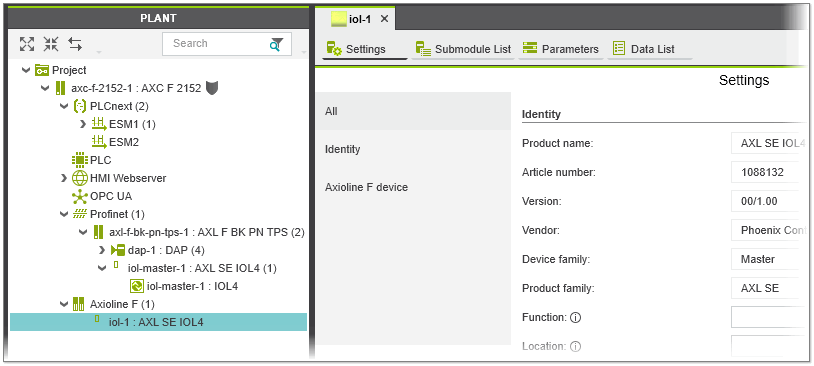
- Double-click the IO-Link master node in the PLANT and adjust the necessary settings in the 'Settings' and 'Parameters' editors.
Configuring the IO-Link ports
The ports of the IO-Link master can be operated in the operation modes 'IO-Link' (port is used for IO-Link communication), 'DI' (port operates like a digital input) or 'DO' (port operates like a digital output). For each IO-Link port, the operation mode can be configured either manually via the master's 'Parameters' editor or, if the port is to be used in IO-Link mode, automatically by assigning an IO-Link device via the master's 'Submodule List' editor.
Distinction between manual and automatic configuration of the operation mode:
- If you manually configure the operation mode of the IO-Link port, the device data such as the device ID, vendor ID, input and output process data length, etc. have to entered manually. If the operation mode is set to 'IO-Link mode', the input and output process data of the device can only be linked in a 58-byte process data block.
- By assigning an IO-Link device to an IO-Link port via the 'Submodule List', the device data such as the device ID and input/output process data length are derived from the corresponding IODD (IO Device Description) file of the device and automatically entered. In addition, the device-specific parameters can be set and the individual process data of the device can be viewed and linked.
Note
For the assignment of an IO-Link device to a port, the IODD file of the device (IO-Link V1.1) must be available and imported in PLCnext Engineer. (See the topic "Importing IODD Files" for details.)
Automatic configuration of IO-Link ports / assignment of IO-Link devices
Proceed as follows to configure the IO-Link ports by assigning an IO-Link device to a port of the IO-Link master:
- If the IODD files of the devices to be assigned to the IO-Link ports are not available in your project, import the files via 'File > Import > Import IODD File(s)'.
- In the PLANT, double-click the IO-Link master under the 'Axioline F' node and select the 'Submodule List' editor. The 'Submodule List' editor shows the list of the ports of the IO-Link master where each table row represents one IO-Link port.
- For each port, select a suitable IO-Link device which you want to operate on the port. To do this, click in the respective 'Type' table cell and select the device from the appearing list (see the following example). The list provides the IO-Link devices for selection that have been imported into your project.
Alternatively, drag the device from the COMPONENTS area onto the desired table row. (In the COMPONENTS area, the imported IO-Link devices are available under the 'Local' folder in the 'Network'
category.)In doing so, the following applies:
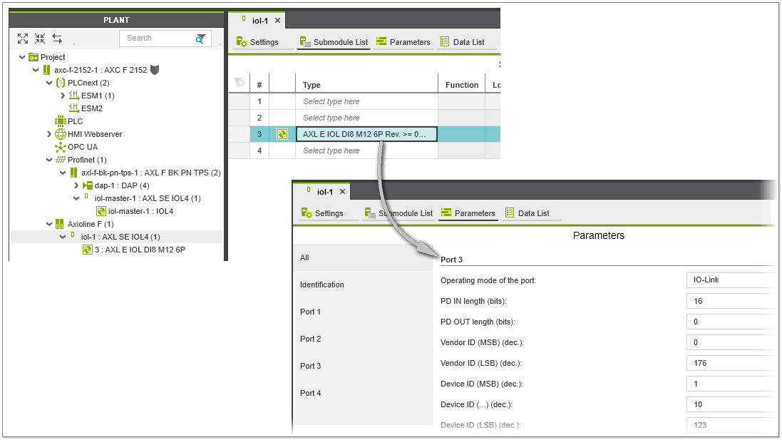
- The operation mode of the port and the device data such as the Device Id, Vendor ID, etc. are automatically entered in the 'Parameters' editor of the IO-Link master (see the following example).
- The individual process data of the device appear in the 'Data List' of the master (the data are also available in the 'Data List' of the IO-Link device).
- In the PLANT, the IO-Link device appears as submodule of the IO-Link master with the corresponding port number preceding the device name. Double-clicking the IO-Link device node in the PLANT opens the corresponding editors in the editors area. Here you can parameterize the device and link the process data to the project variables.
Note
Ensure that the port configuration in PLCnext Engineer corresponds to the actual configuration on the IO-Link master. - Once you have assigned the IO-Link devices, parameterize them in the 'Settings' and 'Parameters' editors of the device (the parameters to be set are derived from the IODD file provided by the manufacturer of the device and may differ for each device). To open the device editors, double-click the IO-Link device in the PLANT and activate the corresponding editor in the editors group. In the 'Data List' editor of the device, link the process data to your project variables.
 Example
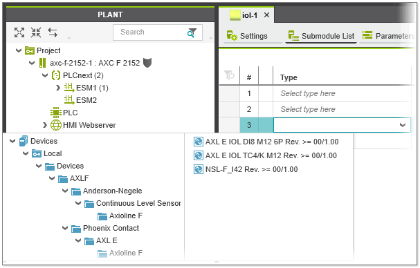
Manual configuration of IO-Link ports (using ports as digital input or output)
| Note
The manual configuration of an IO-Link port is only possible if it is unassigned in the master's 'Submodule List'. To manually set the operation mode for an already configured port, first remove the assigned device as described below. |
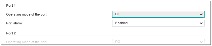
- Open the 'Parameters' editor of the IO-Link master. In the editor, each port is represented by an own parameter group.
- Select the operation mode for the port from the associated 'Operating mode...' list box. If a port is unused, select the operation mode 'Disabled'.
- In the 'Port' group, set the mode-specific parameters. If the port is set to 'IO-Link mode' (port is used for IO-Link communication), enter the standard IO-Link parameters such as the device ID, vendor ID, process data lengths etc. of the device.
- In the 'Data List' of the master, link the process data of the device to the project variables as follows:
- If the operation mode is set to 'IO-Link mode', the input and output process data of the device have to be linked to the 'IN_58Bytes' and 'OUT_58Bytes' process data items (58-byte process data blocks).
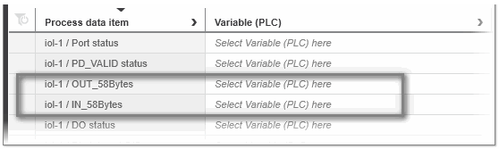
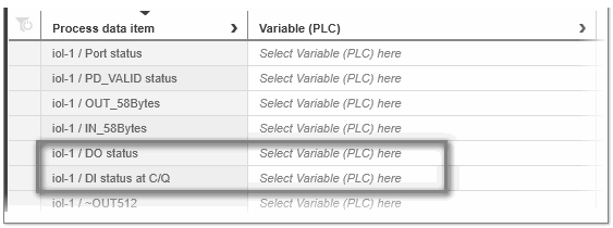
- If the operation mode is set to 'DI' or 'DO' mode, the corresponding process data are combined in one byte (process data items 'DO status' and 'DI status at C/Q'). The bit position in the byte corresponds to the slot number or physical connection of the I/O device.
- If the operation mode is set to 'IO-Link mode', the input and output process data of the device have to be linked to the 'IN_58Bytes' and 'OUT_58Bytes' process data items (58-byte process data blocks).
Writing startup parameters for the IO-Link device
In the IODD file of an IO-Link device, some parameters are defined as startup parameters. The startup parameters are used to configure the behavior of the IO-Link device at startup. These parameters are stored retentively in the flash memory of the device. During startup, the IO-Link master automatically starts up the IO-Link devices and transfers the Axioline F configuration to the IO-Link devices. The Axioline F configuration contains the submodules, devices etc. you have configured in your project and also the device-specific startup parameters.
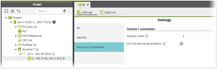
By default, the device-specific startup parameters for the IO-Link device are included in the Axioline F configuration. You can disable the automatic insertion of the startup parameters into the Axioline F configuration and thus exclude the parameters from writing to the IO-Link device by deactivating the 'IO-Link startup parameters' checkbox for the desired IO-Link device. The checkbox is available in the device's 'Settings' editor under the 'Axioline F submodule' category.
Removing IO-Link devices
To remove an IO-Link device from the master configuration, select the 'Delete' context menu command from the IO-Link device node in the PLANT or select the node and press <Del>. Alternatively, select the device in the master's 'Submodule List' and press <Del> or select 'Delete' from the device's context menu.
| Note
An IO-Link device can only be removed, if there are no process data items linked to project variables. |