HMI Configuration Sample
This topic describes how to create an XML configuration file using a simple PLCnext Engineer project as an example.
Note
The example assumes that you are familiar with XML programming and the XML syntax rules. It is recommended to use an XML editor for creating the XML configuration file. The configuration file must conform to the schema provided by Phoenix Contact. |
This chapter includes the following sections:
Example PLCnext Engineer project
The example project contains the following items which are used for the generation of the HMI content based on the sample configuration file. The list only contains the project items which are processed using the configuration file; other items shown in the figures can be ignored.
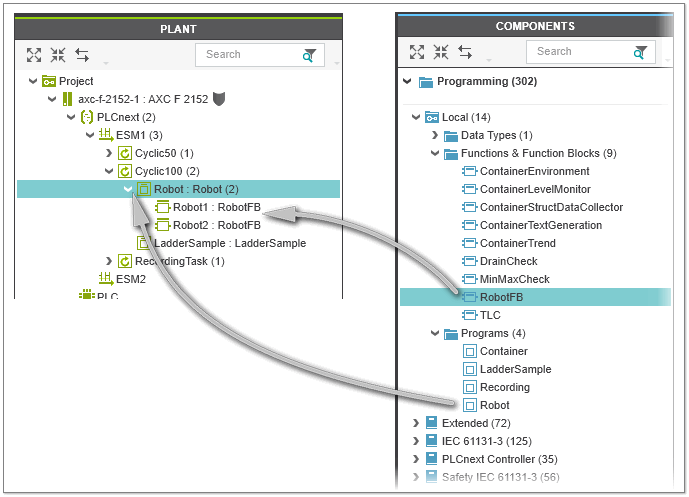
 FB 'RobotFB'
The function block 'RobotFB' is instantiated two times in the program POU 'Robot'. The program POU 'Robot' is assigned to the task 'Cyclic 100'.
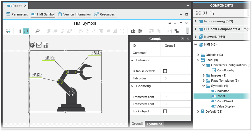
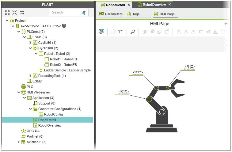
User-defined HMI symbol 'Robot'
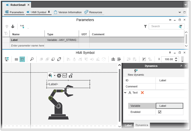
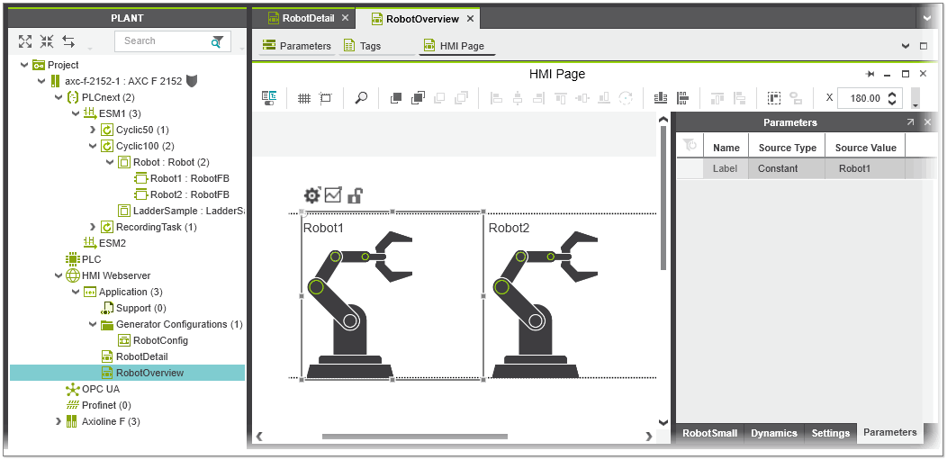
User-defined HMI symbol 'RobotSmall' with symbol parameter 'Label' and 'Text' dynamic
What we want to do
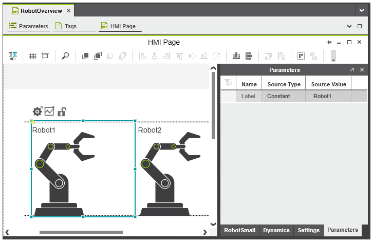
In the example, we are going to create two HMI pages from the project elements described above: the detail HMI page 'RobotDetail' for the FB 'RobotFB' which contains one 'Robot' symbol instance and the overview HMI page 'RobotOverview' which contains a 'RobotSmall' symbol instance for each 'RobotFB'. The creation of the HMI pages and the HMI symbol instances are all triggered by the existence of the 'RobotFB' instances. To distinguish the two 'RobotSmall' instances on the 'RobotOverview' page, the name of the FB (POU) instances ('Robot1' and 'Robot2') are set for the 'Label' symbol parameter.
HMI page 'RobotDetail' with an instance of the 'Robot' symbol
HMI page 'RobotOverview' with two instances of the 'RobotSmall' symbol and configured symbol parameter
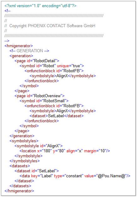
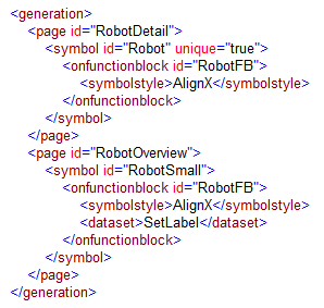
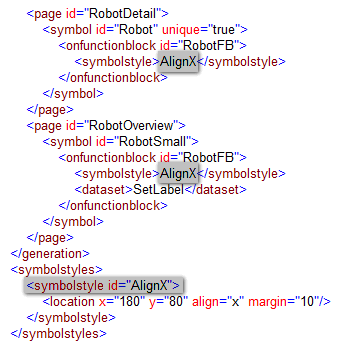
Full XML code
The following shows the full XML code for the sample configuration file. The elements and attributes used are described in the following section.
Description of elements and attributes in the XML file
This section contains an explanation of each element and attribute in the XML configuration file used to create the HMI pages and HMI symbols as described above. The elements and attributes are listed in the order in which they appear in the XML file. For a complete list of the XML elements and attributes you can use in a configuration file, see the topic "HMI Configuration File Elements and Attributes".
Note
All elements and attributes must be written in lowercase. |
Element <hmigenerator>
Root element that contains all other elements in the XML file.
Generating the pages 'RobotDetail' and 'RobotOverview'
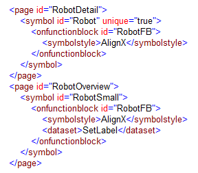
Element <generation>
Element that serves as container for one or more <page> elements used to define the HMI pages to be created.
In the example, the <generation> element contains two <page> elements, one element for the 'RobotDetail' page and one for the 'RobotOveview' page.
Element <page>
Child element of the <generation> element. This element defines the HMI page to be created. The creation of the HMI page is triggered by the existence of an IEC code element (for example, FB instance, program instance, variable, etc.) defined by the descendant <on...> element such as <onfunctionblock>. The element contains the following attribute:
| Attribute | Description | Type / Required |
| id | Unique identifier referencing the HMI page to be created ('RobotDetail' and 'RobotOverview' in the example). The id value is used as name of the HMI page instance. | Type: stringRequired: yes |
In the example, the creation of the HMI pages 'RobotDetail' and 'RobotOverview' are both triggered by the existence of the FB instance 'RobotFB' defined by the descendant <onfunctionblock> element.
Generating the symbol instances 'Robot' and 'RobotSmall' and assigning symbol styles and data values
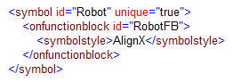
Element <symbol>
Child element of the <page> element. This element defines the HMI symbol instance to be created on the HMI page defined by the parent <page> element. The creation of the HMI
symbol instance is triggered by an IEC code element (for example, FB instance, program instance, etc.) defined by the descendant <on...> element such as <onfunctionblock>. The element contains the following attributes:
| Attribute | Description | Type / Required |
| id | Unique identifier that defines the HMI symbol name as set in the COMPONENTS under the 'HMI' category for which a symbol instance is to be created. The id value appears as object ID in the properties window of the HMI symbol. The value is also used as name of the HMI symbol instance. | Type: stringRequired: yes |
| unique | Specifies whether the HMI symbol instance should be created once or as many times the IEC code element exists that triggers the creation. | Type: boolean true or false (default)Required: no |
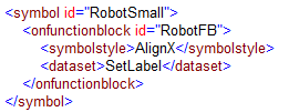
In the example, the 'Robot' symbol instance is created once (unique="true") on the 'RobotDetail' page, even if the triggering FB instance 'RobotFB' (defined by the child element <onfunctionblock>) exists twice in the project. The 'RobotSmall' symbol instance is created twice (unique attribute not used) on the 'RobotOverview' page.
Element <onfunctionblock>
Child element of the <symbol> element. This element defines the FB instance which triggers the creation of the HMI symbol instance on the HMI page. The element contains the following attributes:
| Attribute | Description | Type / Required |
| id | Unique identifier that defines the FB instance that triggers the creation of the HMI symbol instance defined by the parent <symbol> element. | Type: stringRequired: yes |
In the example, the FB instance 'RobotFB' triggers the creation of the HMI symbol instance 'Robot' on the 'RobotDetail' page. 'RobotFB' also triggers the creation of the symbol instance 'RobotSmall' on the 'RobotOverview' page.
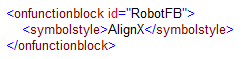
Element <symbolstyle> (child of <onfunctionblock>)
Child element of the <onfunctionblock> element. This element assigns the style definitions referenced by the content of the element to the created HMI symbol instance. The content of the element is the id of the referenced <symbolstyle> element (child element of <symbolsytles>).
In the example, the styles defined by the <symbolstyle> element with id="AlignX" are applied to the 'Robot' symbols instance and both 'RobotSmall' symbol instances.
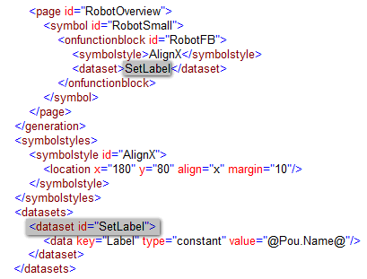
Element <dataset> (child of <onfunctionblock>)
Child element of the <onfunctionblock> element. This element assigns the data definitions referenced by the content of the element to the created HMI symbol instance. Data definitions are used to configure HMI symbol parameters. The content of the element is the id of the referenced <dataset> element (child element of <datasets>).
In the example, the data defined by the <dataset> element with id="SetLabel" are applied to both 'RobotSmall' symbol instances on the 'RobotOverview' page.
Defining symbol styles for the symbol instances
Element <symbolstyles>
Element that serves as container for one or more <symbolstyle> elements.
Element <symbolstyle>
Child element of the <symbolstyles> element. This element is used to assign the style definitions defined by the child elements to the HMI symbol instance. The element contains the following attributes:
| Attribute | Description | Type / Required |
| id | Unique identifier for this symbol style. This is used in the <symbolstyle> element (descendant element of <symbol>) to refer to the styles defined by the <location> child element. | Type: stringRequired: yes |
In the example, the symbol style definition 'AlignX' is referenced in the <symbolstyle> elements of the 'Robot' and 'RobotSmall' symbol instance. This means, the values of the <location> child element are applied to the 'Robot' symbol instance on the 'RobotDetail' page and both 'RobotSmall' symbol instances on the 'RobotOverview' page.
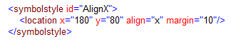
Element <location>
Child element of the <symbolstyle> element. This element is used to position the HMI symbol instance on the HMI page. The element contains the following attributes:
| Attribute | Description | Type / Required |
| x | Defines the horizontal x-coordinate location of the HMI symbol instance on the HMI page relative to the left edge of the page. (Dot used as separator for decimal values.) | Type: stringRequired: yes |
| y | Defines the vertical y-coordinate location of the HMI symbol instance on the HMI page relative to the top edge of the page. (Dot used as separator for decimal values.) | Type: stringRequired: yes |
| align | Defines whether the HMI symbol instances are automatically positioned with a default gap between the symbols on the HMI page. The attribute is used to avoid overlapping of HMI symbol instances on a page which have the same <symbolstyle> assigned. Possible values are 'x' (alignment on the x axis) and 'y' (alignment on the y axis). | Type: stringRequired: no |
| margin | Defines the gap between HMI symbol instances created on the HMI page when aligning symbols using the align attribute. The margin is added to the x- and y-coordinate values. The value is ignored if no align value is specified. | Type:
decimalRequired: no |
In the example, the
'Robot' and 'RobotSmall' symbol instances have an x-coordinate of 180 and an y-coordinate of 80. With align="x", the 'RobotSmall' symbols created on the 'RobotOverview' page (one symbol instance per 'RobotFB') are automatically aligned on the x-axis with a gap of 10 (margin="10") between the symbols.
Setting the HMI symbol parameter of the 'RobotSmall' symbol instances
Element <datasets>
Element that serves as container for one or more <dataset> elements.
Element <dataset>
Child element of the <datasets> element. This element specifies the dataset to be used for the HMI symbol instance. The element contains the following attributes:
| Attribute | Description | Type / Required |
| id | Unique identifier for this dataset. This is used in the <dataset> element (descendant element of <symbol>) to refer to the data defined by the <data> child element. | Type: stringRequired: yes |
In the example, the dataset definition 'SetLabel' with the values of the <data> child element is applied to the 'RobotSmall' symbol instances on the 'RobotOverview' page.
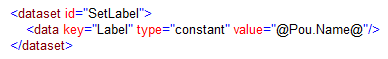
Element <data>
Child element of the <dataset> element. This element is used to set the values of the HMI symbol parameters defined for the HMI symbol. The element contains the following attributes:
| Attribute | Description | Type / Required |
| key | 'Name' of the HMI symbol parameter to be set.If the HMI symbol does not provide the symbol parameter, nothing is done. | Type: stringRequired: yes |
| value | 'Source Value' of the HMI symbol parameter. The 'Source Value' defines the value that is written to the symbol parameter. Placeholders enclosed in @ can be used. | Type: stringRequired: yes |
| type | 'Source Type' of the HMI symbol parameter. The 'Source Type' defines the (data) type of value to be written to the symbol parameter.Possible values are 'constant', 'variable', 'variablepath', 'page', 'pagepath', 'setting', and 'resourcename'. | Type: datatypeRequired: no |
In the example, the symbol parameter 'Label' of the 'RobotSmall' symbol instances are set as follows:
- 'Source Type' = 'constant'
- 'Source Value' = 'Robot1' for symbol instance 1 and 'Robot2' for symbol instance 2 ('@Pou.Name@' is a placeholder for the name of the POU instance which triggers the creation of the symbol instance).