Data Logger Configuration
The DataLogger is a service component of the PLCnext Technology firmware. It can record data from any PLCnext IN or OUT ports. Recorded values are transferred from the GDS to a data sink for recording and storage purposes. The storage of the recorded data is done on the controller. The database is either written to the SD card or kept non-remanent in the controller RAM.
The Data Logger is started and stopped automatically on starting and stopping the firmware, i.e., the PLCnext Technology controller.
The Data Logger tool provides a further possibility of recording data from the running process besides the LOGIC ANALYZER tool. The difference is that PLCnext Engineer must be connected to the controller and the debug mode must be activated to use the LOGIC ANALYZER. The Data Logger, however, performs the data recording independently of PLCnext Engineer and its configuration is not volatile.
You can define several Data Logger sessions, each identified by a unique name.
The configuration of the Data Logger (sessions) can be done via- the 'Data Logger Sessions' editor in PLCnext Engineer, or
- manually via XML configuration files.
| Note
Any modification of the Data Logger configuration is applied after restarting the controller. |
| Further Info
More details on the Data Logger and how to configure it with XML configuration files can be found in the PLCnext Technology User Manual (document number 109324_en_00), chapter "DataLogger". |
How to configure the Data Logger in PLCnext Engineer
To be able to configure Data Logger sessions in PLCnext Engineer, the following must apply:- The controller may be connected or not.
- The controller must not be running. (While the application program is executing, the 'Data Logger Sessions' editor is in read-only mode.)
 Example figure...
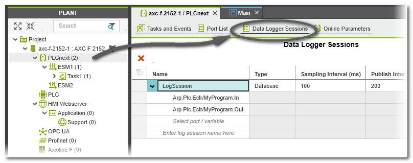
Proceed as follows:
- Double-click the 'PLCnext' node in the PLANT.
- Open the 'Data Logger Sessions' editor.
- To create a new session, enter a new session name (see description of fields below) and press <Enter>.The new session is created with default settings (see table below).
- Configure each recording session by defining the values in a session table row.
See section "Data Logger configuration settings" for details on the parameters to be set. - Add the ports to be recorded under a session table row by selecting the required items in the 'Name' column.
Note
- Only ports that are actually used (i.e., instantiated) in the project can be added to a session.
- Ports can be added to more than one session.
- 'Write and Start' the project to apply the Data Logger configuration with the following command in the Cockpit or the controller context menu in the PLANT:
 The Data Logger is
started automatically executing the configured sessions after the restart of the PLCnext Technology controller.For each defined log session, PLCnext Engineer creates one configuration file pcwe.<sessionname>.dl.config.
The Data Logger is
started automatically executing the configured sessions after the restart of the PLCnext Technology controller.For each defined log session, PLCnext Engineer creates one configuration file pcwe.<sessionname>.dl.config.
On the controller, the configuration files are stored under /opt/plcnext/projects/PCWE/Services/DataLogger/.
| Further Info
The steps how to configure the Data Logger manually via an XML configuration file can be found in the PLCnext Technology User Manual. |
Data Logger configuration settings
For each Data Logger session, the following configuration parameters must be set in the 'Data Logger Sessions' editor. No parameter may remain undefined.
| Parameter | Meaning | ||
|---|---|---|---|
| Name | Identifies the Data Logger session. The name must be unique within the project. The name must consist of normal letters and the characters "-", ".", and "+". Other special characters are not allowed. |
||
| Type | Defines the name of the data sink where the recorded data is stored. For each configured Data Logger session, one data sink is created.Possible values are:
|
||
| Sampling Interval (ms) | Defines the interval (in ms) in which the Data Logger subscribes values. Value range: 0 up to 65535 Default value: 100 ms |
||
| Publish Interval (ms) | Defines the interval (in ms) in which the data is transferred from the data buffer to the data sink. Note that the data publishing is not
performed within the real-time context. See next table row for further information. Value range: 1 up to 18446744073709551615 Default value: 200 ms |
||
| Buffer Capacity (cycles) | Determines the size of the data buffer (in no. of cycles) where the recorded values are cached before they are forwarded to the specified data sink. Value range: 0 up to 65535 Default value: 10Background: In each cycle, the values of all recorded data items of a task are stored temporarily in this ring buffer. The capacity of the ring buffer determines the maximum number of task cycles that can be recorded before the data must be transferred from the buffer to the data sink. The transfer from the buffer to the data sink is referred to as publishing. |
||
| Rollover | Defines the handling of data sink files.
|
||
| Write Interval | Specifies how many data
records are published to the data sink before these values are written to the file on the SD
card.The parameter is only relevant if 'Database' is set as 'Type'. Before closing the database or when the controller is switched off, all recorded values
that have not yet been transferred are written to the SD card.
|
||
| Max File Size | Defines the maximum memory size of the log file in bytes. Value range: 16384 up to 150000000 bytes Default value: 5000000
|
||
| Max Files | Defines the maximum number of rolling files.
The value is only relevant, if the 'Rollover' checkbox is activated. When the maximum number of files is
reached, the oldest file will be deleted. The file index of the closed files will be counted
up further.
Possible values: Value range: -1 up to 4294967295 Default value: -1.
|
||
| Store Changes | Defines the recording mode.
|
||
| Delete Ratio (%) | Defines the percentage amount of the maximum memory size to be deleted for the logging of new data before new data is written into
the database. The old data is deleted when the value that is defined via the Max File Size parameter is reached and the 'Rollover' checkbox is not activated. Value range: 1 to 100 (integer value) Default value: 30 |
||
| Timestamp Format | Possible values:
The timestamp is created in the task cycle based on the system time of the controller. It is set at the start of the task (task executing event) and maps exactly the cycle time of the task. As a result, the timestamp value of the following task cycle is increased by one cycle duration. The time resolution has a precision of 100 ns.Despite the format, all timestamps are reported using the UTC timezone. The implementation and internal representation complies to the .NET DateTime class, see Documentation of DateTime Struct on https://docs.microsoft.com. |
||
| Trigger Condition | Defines whether the value sampling is done in the context of a selected task or not.
|
||
| Task Context | The field is only active if the checkbox 'Trigger Condition' is marked.Select the task in which sampling is to be performed from a drop-down list. The drop-down list offers all task types for selection. The task defines the update rate of the recorded values. Values are subscribed after each cycle of the selected task. The properties of the set task influence the Data Logger session because the subscription rate depends on the cycle time of the synchronization task. If an 'Idle Task' is selected, the visualized values may be inexact or outdated since the cycle time of the 'Idle Task' may vary (depending on the other user tasks on the controller). An 'Event Task' may be executed not cyclically depending on the defined event. |
||
| Pre Cycles | The field is only active if the checkbox 'Trigger Condition' is marked.Specifies the number of sampling cycles recorded before the trigger event (default value = 10 ms). As soon as the trigger event has occurred, the data recorded during the "pre-trigger cycles" are stored. | ||
| Post Cycles | The field is only active if the checkbox 'Trigger Condition' is marked.Specifies the number of sampling cycles recorded after the trigger event (default value = 10 ms). As soon as the trigger event has occurred, the data recorded is continued during the number of defined "post-trigger cycles". If this number has been reached, the session is stopped automatically. | ||
| Operand 1 and Operand 2 | The fields are only active if the checkbox 'Trigger Condition' is marked.Variable or port used as trigger condition.Depending on the set operation, one or two operands have to be defined.Open the drop-down list which offers only data items of a suitable data type according to the 'Operation' selected. To define a constant as operand, enter a numeric value, or a Boolean value (FALSE or TRUE). | ||
| Operation | The field is only active if the checkbox 'Trigger Condition' is marked.Select an 'Operation' from the drop-down list. Depending on the set operation, one or two 'Operands' have to be defined. |


Evaluation of the database for consistent data
By evaluating the ConsistentDataSeries database flag in your application, you can monitor the consistency of the recorded data.
Background: Incomplete data recording (for example due to performance reasons or a memory overflow) is indicated in the database column ConsistentDataSeries:- ConsistentDataSeries = 0 indicates that a data gap occurred during the recording of the preceding data series. The first data series always has the value 0 because there is no preceding data series as reference.
- ConsistentDataSeries = 1 indicates that the data is recorded without a gap related to the preceding data series. The data series is consistent to the preceding data series.