Feature Overview: Graphic Editor
PLCnext Engineer provides a powerful graphic editor to develop the application program in the graphical IEC 61131-3 programming languages FBD, LD and SFC. Furthermore, NOLD (Network-Oriented Ladder)
and SNOLD worksheets can be programmed.
NOLD is an FBD/LD variant with the same syntax but a network-oriented behavior of the editor. See topic "Programming FBD/LD, NOLD and SNOLD
" for details.
Safety-related code can only be programmed in SNOLD worksheets. SNOLD is the safety-related variant of NOLD. This means, basically the same syntax and objects are used but, compared to NOLD, some restrictions apply.
This topic contains the following sections:
- Features of the graphic editor at a glance
- FU/FB symbol indicates origin
- Expanded / collapsed editors area
- Pin/unpin particular editors
Features of the graphic editor at a glance
- Mixing of LD and FBD programming languages (in FBD/LD worksheets, NOLD and SNOLD worksheets).Even SFC code can be extended by FBD/LD objects.
- NOLD: network layout is arranged automatically and cannot be modified by the user, i.e., objects and lines cannot be moved (in contrast to the free graphic editor).
- SNOLD: safety-related network-oriented graphic editor. Basically, the SNOLD editor works like the NOLD editor and provides additional safety-related features such as continuous verification of the worksheet data consistency, signal path analysis, verification of code networks, etc. Refer to the topic "Similarities and differences between FBD/LD, NOLD and SNOLD" for details.
- Continuous automatic compiler checks in the background.While editing code, the compiler continuously checks the syntax of the code. Any detected errors are marked in the code worksheet. Additionally, errors are listed in the MESSAGES window and indicated in the status bar.
- Insertion of code objects, such as functions, function blocks from the COMPONENTS area, via keyboard (Intellisense function), toolbar or context menu.
- Variable declaration via in-place button or context menu.After inserting a new variable which is not yet declared or after inserting a new LD object with unassigned variable, you can add the new variable to the relating variables table as follows: right-click the variable or LD object in the code worksheet and select 'Create New Variable > Variable type' from the context menu or click one of the in-place buttons. Depending on the POU type (program, function, FB) different variable types can be declared.
 In-place buttons for declaring variables:
See also topic "Variable Declaration Keywords" for details. - Function block instance declaration via in-place button or context menu.After inserting a function block instance into the code worksheet, for example, via drag & drop from the COMPONENTS area, you can create the new function block instance declaration in the relating variables table as follows: right-click the function block in the code worksheet and select 'Create New Function Block Instance' from the context menu or click the in-place button:

- FBD/LD worksheets and SFC worksheets: Auto-routing of connection lines.In NOLD and SNOLD, the network layout is prescribed by the editor and cannot be modified by the user.
- Simply double-click on a function block POU, function POU, method, or action/transition/interlock, to open the editor group of the POU (possible in offline and online mode).
- Auto-connection of objects on insertion.
- Direct access to further object-specific commands using the in-place buttons.
- Keyboard operation.
- Display of execution order in code worksheets.You can display the order in which the objects within a code worksheet are executed when running the program on the controller.
- Find and replace functionThe 'GLOBAL FIND AND REPLACE' control available in the Cross Function Area can be used to search for certain strings and replace them by another string in all editors.
-
ZoomingThe zoom factor of the graphical worksheet can be changed using the zoom options in the lower right corner in the status bar.
 Zooming in or out in a graphical worksheet is also possible by just holding down the <Ctrl> key and using the wheel on your mouse to zoom in or out.
 - Panning the worksheet contentIn a graphical worksheet, you can pan around the worksheet, i.e., move the worksheet focus by holding down the mouse wheel or middle mouse button and dragging the mouse.
- Overview map facilitates orientation and navigationIn graphic code worksheets, a schematic overview map is displayed in the lower right corner. In this map, the currently displayed worksheet area is shown as darker rectangle thus facilitating orientation in large worksheets.
You can navigate in the worksheet by dragging this area in the map.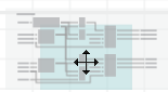
- EN/ENO (optional conditional execution of functions and function blocks) can be used in FBD. EN/ENO is not supported in safety-related code.Refer to the help topic "Execution Control: EN/ENO" for details.
- Debug/programming modeThe editor supports two modes. In programming mode you edit worksheets. By attaching PLCnext Engineer to the running application process, the debug mode is activated. The debug mode assists you in carrying out function testing when commissioning the project by enabling you to display online values and execute debug commands.
Further Info
For information on commissioning the application and monitoring the application execution in debug mode, refer to the topic "Commissioning the Application: From Compiling to Debugging ‣ Controller Commissioning: From Compiling to Debugging
×‣ Safety PLC Commissioning: From Compiling to Debugging
×".


FU/FB symbol indicates origin
The block color and the icon in the upper left corner of the symbol indicate the origin of functions/function blocks:
| Symbol / color | Origin of the POU |
|---|---|
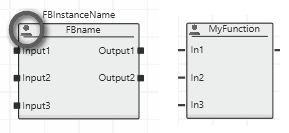 | User-defined function/function block which is provided in the current project (COMPONENTS 'Programming' hierarchy, folder 'Local | Functions & Function Blocks'). |
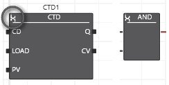 | Function/function block which is provided by default by the programming system. Such FUs/FBs are contained in separate folders in the COMPONENTS 'Programming' hierarchy, such as:
 |
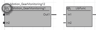 | Function/function block which is contained in a user library added to the project. Such FUs/FBs are contained in separate folders in the COMPONENTS 'Programming' hierarchy which has the same name as the library. Example:
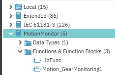 |
Expanded / collapsed editors area
PLCnext Engineer provides two possibilities for maximizing the editors area. Both are executed by the maximize icon  which is available in each editor window (see (1) in the following figure) and in the tab bar of the editors area (2):
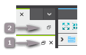
Maximize icon (1) enlarges the current editor window to fit the entire screen.
Icon (2) at the right side in the tab bar of the editors area maximizes the entire editors area including the editor group tab bar. This command is also available in the 'View' menu.
In both cases, PLANT and COMPONENTS are hidden. By hovering the mouse pointer to the title bar of the hidden PLANT or COMPONENTS area, it is expanded. Double-clicking an element in the expanded area first opens the related editors group and then hides the area again.
To exit the maximized editor mode, click the respective maximize icon again.
| Note
Both maximize functions can be combined. |
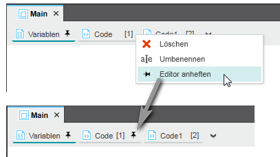
Pin/unpin particular editors
You can open several editor windows in the editors area at the same by pinning them. Only if pinned, an editor window remains visible when another editor window is opened. If an editor window is unpinned, it disappears when you open another editor.
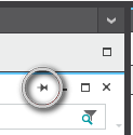
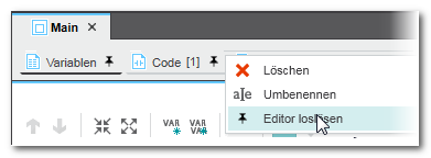
To pin an editor window, right-click the editor window tab and select 'Pin Editor' from the context menu. Pinned editors are marked with the pin icon on the tab. To unpin, select 'Unpin Editor' from the context menu. Both commands are also available as icons in the upper right corner of the editor window:  and
and