Redundancy Overview
The 'Redundancy overview' shows the redundant physical topology. Devices with enabled redundancy (for example, devices with enabled (R)STP or MRP) are represented in the physical topology by specific symbols (see below). The device tooltip shows which protocol is enabled on the device. Blocked ports are represented by specific port symbols. The port state is shown in the port tooltip. Non-redundant devices are greyed out in the topology.
Symbols specific to the 'Redundancy overview'
| Note
You can switch the display of the devices between two modes: standard and individual. In standard mode, the device symbol as listed in the following table are used for the representation of the devices. In individual mode, the device icon stored in the device description file of the device (e.g., FDCML, GSDML, etc.) is shown as device symbol. To switch the display, click the  button in the toolbar of the 'Physical Topology' editor (see also the section "Enable / disable display of device graphics" for further details). button in the toolbar of the 'Physical Topology' editor (see also the section "Enable / disable display of device graphics" for further details). |
| Symbol | Device |
|---|---|
 | Redundancy member |
 | Blocked port |
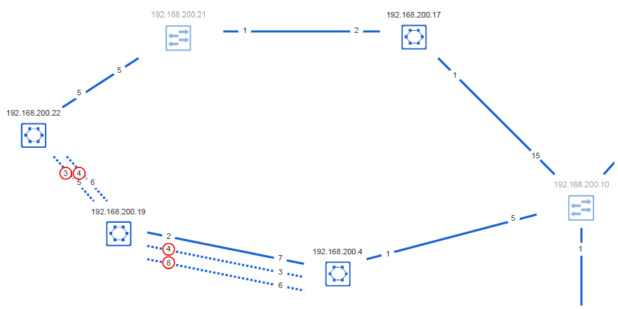
Example of a redundancy topology