Safety PLC Diagnostics out of the Safety Cockpit
Besides the main Safety PLC control functions, the Safety Cockpit displays essential diagnostic information on the Safety PLC.
 How to open the Safety PLC Safety Cockpit

- Make sure that the Safety PLC is set as target system (not 'Safety PLC simulation').
- On the Safety Cockpit toolbar, click the 'Connect to Safety PLC' button to establish:

Available status information and diagnostics (Safety PLC messages)
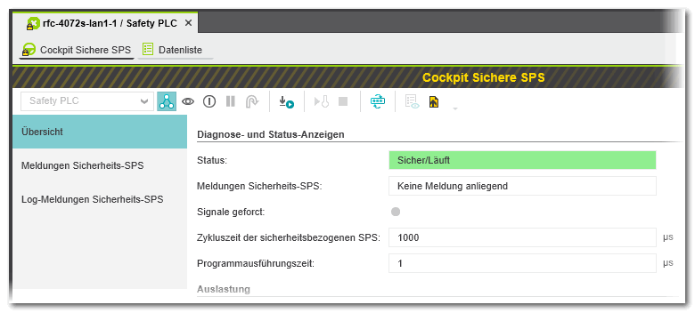
The information is divided into several sections which can be selected via the list on the left. The shown information depends on the controller type involved. Example:
| Note
Status information read from the device is only displayed while the communication connection is established between the Safety PLC and PLCnext Engineer. Otherwise, only project-related (offline) information is shown here. |
'Overview' page
The page 'Overview' provides the following information structured in different sections:
'Diagnostic and status indicator' section
| Element | Meaning | Refresh interval |
|---|---|---|
| Status | Indicates the operational Safety PLC state. The state is also reflected by the Safety PLC icon in the PLANT. | 500 ms |
| Fail | Indicates whether the Safety PLC has written an entry to the error stack of the safety-related runtime (SafeOS). If the LED is on, you can read the errors from the error stack and display them in the 'Safety PLC messages' page of the Safety Cockpit. Refer to the description below. | 500 ms |
| Signals forced | Indicates whether currently I/O variables are forced on the Safety PLC. | 500 ms |
| Safety PLC cycle time | Indicates the cycle time of the Safety PLC. | Once after connecting to the Safety PLC. |
| Program execution time | Time period needed from the beginning of one control cycle to the beginning of the next cycle and pure execution time needed to process the safety-related program code.Using these values and further information contained in the Safety PLC manual, you are able to calculate the overall system response time (SFRT). | Once after connecting to the Safety PLC and after writing a safety-related project. |
'Utilization' section
| Element | Meaning | Refresh interval |
|---|---|---|
| Program memory | Indicates the usage of the program memory. | Once after connecting to the Safety PLC and after writing a safety-related project. |
| Data memory | Indicates the usage of the application data memory. | Once after connecting to the Safety PLC and after writing a safety-related project. |
'Safety PLC project information' section
| Element | Meaning | Refresh interval |
|---|---|---|
| Name | Safety-related project currently stored on the Safety PLC. | Once after connecting to the Safety PLC and after writing a safety-related project. |
| Last build date | Time stamp of the project currently stored on the Safety PLC. (Representation acc. to the system locale set for your PC.) | |
| Checksum | Checksum of the project currently stored on the Safety PLC. | |
| User | User who has written the project to the Safety PLC. |
'Engineering project information' section
| Element | Meaning | Refresh interval |
|---|---|---|
| Name | Safety-related project currently open in PLCnext Engineer. | Once after opening the Cockpit and the after 'Save As...' command. |
| Last build date | Time stamp of the project currently open in PLCnext Engineer. (Representation acc. to the system locale set for your PC.) | Once after opening the Cockpit (only if a valid compiled project is available at that point of time) and after each successful project build. |
| Checksum | Checksum of the project currently open in PLCnext Engineer. | Once after opening the Cockpit and after each modification of safety-related data in the project. |
| User | User who is currently logged-on to Windows. | Once after opening the Cockpit |
'Version information' section
| Element | Meaning | Refresh interval |
|---|---|---|
| Firmware version | Version number of the safety-related firmware of the connected Safety PLC. | Once after connecting to the Safety PLC. |
| Serial number | Serial number of the connected Safety PLC. | Once after connecting to the Safety PLC. |
'Safety PLC messages' page
The 'Safety PLC messages' editor page lists the errors which have been read from the error stack of the Safety PLC.
In case of a runtime error, the Safety PLC writes an entry to the error stack of the safety-related runtime (SafeOS). The 'Fail' LED on the 'Overview' page of the Safety Cockpit indicates that an error has occurred and that you can read the errors from the error stack and display them here in the 'Safety PLC messages' editor.
Click the button  on the Safety Cockpit toolbar to read the error stack and display the messages in the Safety Cockpit.
The help chapter "Error Messages of the Safety PLC" in the Error Catalog provides information on the possible error messages.
'Safety PLC log messages' page
The 'Safety PLC log messages' editor page lists the entries which have been read from the log book of the Safety PLC. In the log book, the Safety PLC records device-related events such as state changes, errors, and so on.
While you are logged on to the Safety PLC and the Safety PLC is in Stop state, click the button  on the Safety Cockpit toolbar to read the log book and display the messages.