Scanning the Network for Profinet Devices
For scanning the network for Profinet devices, the project must already contain a controller with Profinet controller. Refer to the topics "Scanning the Network for a Controller (Controller-based Template)" or "Scanning the Network for a Controller (Empty Project)" for detailed procedures.
| Note
For a network scan as described below, it is not necessary to manually establish a communication connection before the scan. This is done automatically by PLCnext Engineer. |
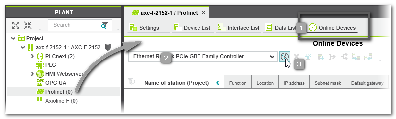
- Double-click the 'Profinet' node.
In the editors area, open the 'Online Devices' editor (see (1) in the figure below). - In the drop-down list (2), select the LAN adapter of your computer which is connected to the controller network to be scanned.
- Click the 'Scan the network' button (3) on the 'Online Devices' toolbar.
 The network is scanned and found Profinet devices are listed in the table.
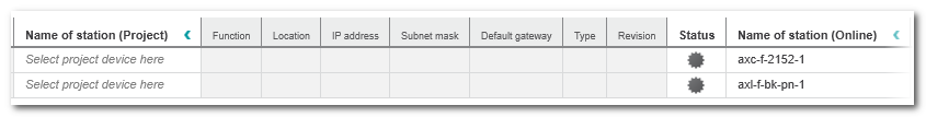
The columns left of the 'Status' column represent the configuration edited in the project. The columns are empty as no Profinet device has yet been added to the project.TheNote
If your project controller can be used as both the Profinet controller and Profinet device at the same time, the controller is also found as device and listed in the table (as shown in the example above). icon in the 'Status' column indicates that the scanned device is not yet contained in the project.
 - Select the table line with the found device and execute the command 'Add to Project' from the context menu or click the following toolbar button:
 If a scanned device cannot be uniquely identified because, for example, more than one matching device type is available in the COMPONENTS area ('Device' or 'References' category), the 'Station structure preview' dialog appears. In the dialog, select the 'Type' of the scanned device from the drop-down list and confirm to continue.
Note
Only add a controller as Profinet device if it is not the project controller. Otherwise, the controller would be used as its own child element. - After adding the device to the project, the communication connection 'Status' may switch to 'Warning' because the communication settings of the scanned device do not match the (default) communication settings in your project.
 In this case, proceed as follows:
Select the table line of the device with 'Warning' status and execute one of the following commands from the context menu or click the related toolbar button:- Command 'Apply the online device settings to the project device settings' or toolbar button:
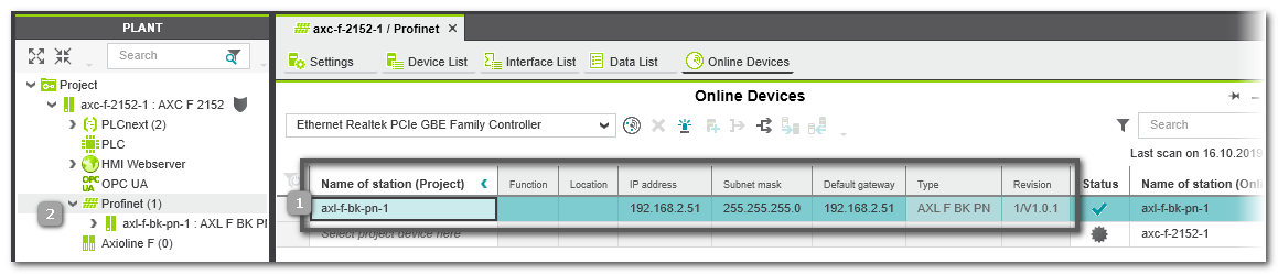
 The communication settings configured in the scanned device are transferred to the project. The 'Online Devices' table is updated accordingly on project side. The 'Status' of the communication connection between PLCnext Engineer and the device is set to 'OK' (green). See (1) in the figure below.
Note
After reading the IP address from the scanned device, an error message may be output that the IP range configured in your project does not match the read IP address. Open the 'Settings' editor of the 'Project' node and adapt the IP range accordingly. - Command 'Apply the project device settings to the online device settings' or toolbar button:
 The communication settings configured in the project are transferred to the scanned device. The 'Online Devices' table is updated accordingly on online side and the communication status is set to 'OK'.
- Command 'Apply the online device settings to the project device settings' or toolbar button:
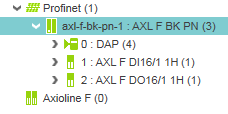
The device is added as node in the PLANT using its configured device name (2).
Profinet I/O modules which are connected to this device are also inserted below the device node.
Example:
Double-clicking the Profinet device node opens the properties providing the 'Module List' editor. In this table, all found Profinet I/O modules are listed.
- By scanning the Profinet network ('Read Profinet modules' in the context menu of the device node in the PLANT),
- or by selecting them in the 'Module List' (station editor).
- or by dragging them from the 'Devices' category of the COMPONENTS area.
 Overview: status icons in the device table


| Further Info
Continue with configuring and parameterizing new devices, e.g., for editing the device IP address. |