Details of the application example
This section describes a possible application where the function block is used to implement a test function for a safety-related sensor during operation.
The function block must only be used in an actual application once a risk analysis has been conducted.
Details of the risk category/SIL/PL have not been included here, as classification is always based on the application in which the function block is used.
| Hinweis
The use of the function block alone is not sufficient to execute the safety-related function according to the Cat./SIL/PL determined by the risk analysis. In conjunction with the safety-related I/O device used, additional measures must be taken to meet the requirements of the safety-related function. These include, for example, the appropriate wiring and parameterization of the inputs and outputs as well as measures to exclude (design out) errors that cannot be detected. For additional information, please refer to the documentation provided with the safety-related I/O device used. |
| Hinweis
Refer to the notes in the User Manual on proper electrical connection of the Sicherheitssteuerung and the extension modules (e.g., connecting the safety-related sensor). |
Light curtain with single-channel connection
This example describes how a light curtain is connected to the safety-related SF_TestableSafetySensor function block using a single-channel arrangement. The function block is connected as follows:
- The function block is perpetually activated by the TRUE constant at the Activate input.
- The function block output S_TestOut outputs the start signal for the sensor test to the sensor. The global I/O variable TOut_OS is assigned to the output terminal 1.1 of the safety-related output device PSDO, to which the test input of the sensor is connected in turn.
- The status signal of the sensor is connected to input terminal 1.1 of the safety-related input device PSDI 1 and assigned to the global I/O variable OS_TSS_In, which is connected in turn to the function block input S_OSSD_In.
- An S1 button for requesting the sensor test is connected to input terminal 1.1 of the standard input device. The signal is assigned to the global I/O variable S1_Start_In, which in turn is connected to the StartTest input of the function block.
- The input S_StartReset = SAFEFALSE specifies a start-up inhibit after the Sicherheitssteuerung has been started up and/or after the function block has been activated. In addition, S_AutoReset = SAFEFALSE specifies a restart inhibit for the function block after the SAFETRUE signal returns at the S_OSSD_In input (light beam of the safety-related sensor is no longer interrupted). Both inhibits are only removed when there is a positive signal edge at the Reset input.
To this end, the S2 reset button is connected to input terminal 3.1 of the standard input device DI 1. Its signal is assigned to the global I/O variable S2_Reset_TSS, which in turn is connected to the Reset input of the function block.
| Hinweis
The enable output S_OSSD_Out of the safety-related SF_TestableSafetySensor function block is directly connected to a global I/O variable or to an output terminal of the application via additional safety-related functions/function blocks. The function block output TestPossible signals whether a test is possible and the TestExecuted output indicates whether the test was performed successfully or is currently in progress. Both outputs are connected to standard variables and can thus be processed in the higher-level standard controller. SafetyDemand signals the status "safety function requested". Connect the SafetyDemand output to an output terminal of your application, either directly or via other standard functions/function blocks. ResetRequest signals whether a reset request by the operator is required to continue. Connect the ResetRequest output to a signal lamp, for example. |
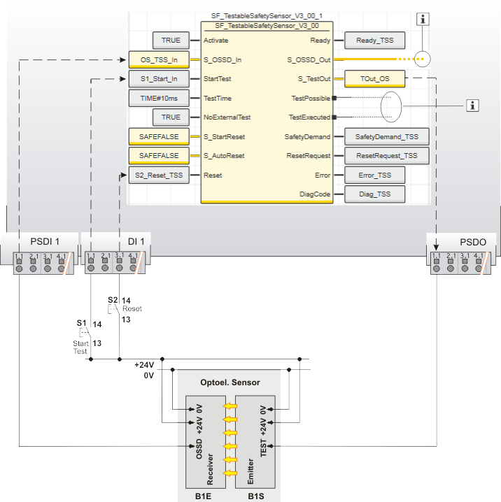
| S1 | Start test |
| S2 | Reset |
| B1 | ESPE - optoelectronic sensor |
| B1S | Emitter |
| B1E | Receiver |
 | See note above the illustration. |