Additional signal sequence diagrams
Temporary intermediate states are not illustrated in the signal sequence diagrams. Only typical input signal combinations are illustrated in these diagrams. Other signal combinations are possible.
The most significant areas within the signal sequence diagrams are highlighted in color.
| Weitere Infos
The diagram found in the overview for this function block must also be taken into account. |
Unsuccessful sensor test followed by external manual sensor test, start-up inhibit and restart inhibit active
This diagram is based on a typical method of connecting the safety-related SF_TestableSafetySensor function block. An unsuccessful sensor test is shown, followed by a manual test.
The following assumptions apply:
- S_StartReset = SAFEFALSE: Start-up inhibit after the function block has been activated and the Sicherheitssteuerung has started up
- S_AutoReset = SAFEFALSE: Restart inhibit if the light beam of the safety-related sensor is no longer interrupted (SAFETRUE signal returns at the S_OSSD_In input).
- NoExternalTest = FALSE: When a sensor test is unsuccessful, the external manual sensor test is supported and requested.
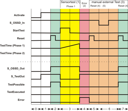
| (1) | Sensor test with one test phase: Phase 1 |
| (2) | Errors |
| (3) | Manual external test |
| (4) | Reset |
| (5) | Light beam interrupted |
| 0 | The function block is not yet activated (Activate = FALSE). As a result, all outputs are FALSE or SAFEFALSE. | |
| 1 | The function block is activated (Activate = TRUE). Even though at the time of function block activation, the S_OSSD_In input (status of the connected sensor) is SAFETRUE, the S_OSSD_Out output remains SAFEFALSE, as a start-up inhibit (S_StartReset = SAFEFALSE) is specified. As there is no active sensor test, the S_TestOut output switches to SAFETRUE immediately. The TestPossible output remains FALSE as the active start-up inhibit means sensor tests are not possible. |
|
| 2 | The start-up inhibit is removed by a positive edge at the Reset input. Since input S_OSSD_In = SAFETRUE (the light beam of the connected sensor is not interrupted), the S_OSSD_Out output switches to SAFETRUE: The sensor does not request a safety-related function (e.g., shutdown).It also becomes possible to perform sensor tests when the start-up inhibit is removed (TestPossible output becomes TRUE). |
|
| 3 | The sensor test starts with sensor test phase 1 when there is a positive edge at the StartTest input. The S_OSSD_Out output remains SAFETRUE during the sensor test to avoid interrupting operation.The S_TestOut output becomes SAFEFALSE to start the test for the connected sensor. The TestPossible output is FALSE during the active test, as two sensor tests cannot be performed at the same time. | |
| 4 | The set monitoring time TestTime elapses without the connected sensor providing the correct response (i.e., a SAFEFALSE signal at the S_OSSD_In input). S_OSSD_In remains SAFETRUE instead.The function block concludes the unsuccessful sensor test after the end of sensor test phase 1, outputs an error message (Error = TRUE), and switches the S_OSSD_Out output to SAFEFALSE. The S_TestOut output also becomes SAFETRUE again at this point. | |
| 5 | The NoExternalTest = FALSE setting means that an external manual sensor test (see phases 5 to 7) needs to be carried out following an unsuccessful sensor test.This manual sensor test is initiated by a positive edge at the Reset input. This causes the Error error output to switch back to FALSE. The S_OSSD_Out output remains SAFEFALSE, however, as the manual sensor test is still outstanding. The TestPossible output also remains FALSE, as sensor test requests are not permitted under these circumstances. |
|
| 6 | The light beam of the sensor is interrupted manually, the S_OSSD_In input becomes SAFEFALSE. This interruption of the light beam is part of the manual sensor test, which means that the S_OSSD_Out output first remains SAFEFALSE. The TestPossible output also remains FALSE, as sensor test requests are still not permitted. |
|
| 7 | Manual interruption of the light beam ceases and the S_OSSD_In input becomes SAFETRUE again. The reset button connected to the Sicherheitssteuerung is pressed once more to end the manual external sensor test. This means the manual sensor test has been completed successfully and the restart inhibit is removed. The S_OSSD_Out output becomes SAFETRUE immediately. The TestPossible output also becomes TRUE, thereby signaling that a new sensor test can be requested.
|
Interruption of the light beam during sensor test phase 2 with deactivated restart inhibit
This diagram is based on a typical method of connecting the SF_TestableSafetySensor function block. An incomplete sensor test is shown: the detection area of the sensor is covered during sensor test phase 2 and the light beam of the sensor remains interrupted after test phase 2. After having removed the interruption, the deactivated restart inhibit allows the automatic restart without manual reset.
The following assumptions apply:
- S_StartReset = SAFEFALSE: Start-up inhibit after the function block has been activated and the Sicherheitssteuerung has started up
- S_AutoReset = SAFETRUE: No restart inhibit if the light beam of the safety-related sensor is no longer interrupted (SAFETRUE signal returns at the S_OSSD_In input). This also applies to interruptions during sensor test phase 2.
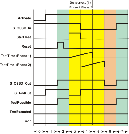
| (1) | Sensor test with two test phases |
| 0 | The function block is not yet activated (Activate = FALSE). As a result, all outputs are FALSE or SAFEFALSE. |
| 1 | The function block is activated (Activate = TRUE). Even though at the time of function block activation, the S_OSSD_In input (status of the connected sensor) is SAFETRUE, the S_OSSD_Out output remains SAFEFALSE, as a start-up inhibit (S_StartReset = SAFEFALSE) is specified. As there is no active sensor test, the S_TestOut output switches to SAFETRUE immediately. The TestPossible output remains FALSE as the active start-up inhibit means sensor tests are not possible. |
| 2 | The start-up inhibit is removed by a positive edge at the Reset input. Since input S_OSSD_In = SAFETRUE (the light beam of the connected sensor is not interrupted), the S_OSSD_Out output switches to SAFETRUE: the sensor does not request a safety-related function (e.g., shutdown).It also becomes possible to perform sensor tests when the start-up inhibit is removed (in other words, the TestPossible output becomes TRUE). |
| 3 | The sensor test starts with sensor test phase 1 when there is a positive edge at the StartTest input. The S_OSSD_Out output remains SAFETRUE during the sensor test to avoid interrupting operation.The S_TestOut output becomes SAFEFALSE to start the test for the connected sensor. The TestPossible output is FALSE during the active test, as two sensor tests cannot be performed at the same time. |
| 4 | The connected sensor reports the SAFEFALSE state at the S_OSSD_In input within the set monitoring time TestTime. This is in line with correct behavior. As a result, the S_OSSD_Out output remains SAFETRUE and no error message is output (the Error output remains FALSE).The switch from SAFETRUE to SAFEFALSE at the S_OSSD_In input starts the second monitoring timer TestTime (2). Phase 2 of the sensor test is now active, which means that the S_TestOut output switches back to SAFETRUE.As before, the enable output is SAFETRUE (normal operation). |
| 5 | During sensor test phase 2, the connected sensor is interrupted, for example, by an object or a worker's hand. As a result, the signal at the S_OSSD_In input remains SAFEFALSE even after the set monitoring time TestTime has elapsed.The S_OSSD_Out output remains SAFETRUE at first, as the sensor test phase 2 is not yet completed (no shutdown required). The Error output remains FALSE, as the interruption of the light beam is not considered as an error under this condition. |
| 6 | The light beam of the connected sensor remains interrupted after phase 2 of the sensor test is completed (S_OSSD_In input remains SAFEFALSE). Therefore, the function test could not be completed successfully and the correction function of the sensor is not confirmed. Output TestExecuted thus remains FALSE and the S_OSSD_Out output switches to SAFEFALSE, i.e., shutdown is requested. |
| 7 | The light beam of the sensor is no longer interrupted, the signal at input S_OSSD_In becomes SAFETRUE again. As the restart inhibit is deactivated by S_AutoReset = SAFETRUE, no reset of the function block is required to switch the S_OSSD_Out enable output to SAFETRUE (shutdown no longer requested, normal operation).The TestPossible output also becomes TRUE, thereby signaling that a new sensor test can be requested. |