| Detailed information |  Signal sequence diagram Signal sequence diagram
This diagram is based on a typical method of connecting the safety-related SF_TestableSafetySensor function block. The following assumptions apply:
-
S_StartReset = SAFEFALSE: Start-up inhibit after the function block has been activated and the Sicherheitssteuerung has started up.
-
S_AutoReset = SAFEFALSE: Restart inhibit if the safety light beam of the sensor is no longer interrupted (SAFETRUE signal returns at the S_OSSD_In input).
-
NoExternalTest = TRUE: No additional manual sensor test is required in the event of an error occurring during the sensor test phases performed by the function block.
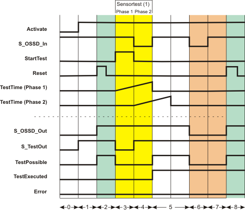
| (1) | Sensor test with two test phases: Phase 1 and phase 2 |
| 0 | The function block is not yet activated (Activate = FALSE). As a result, all outputs are FALSE or SAFEFALSE. |
| 1 | The function block is activated (Activate = TRUE).
Even though at the time of function block activation, the S_OSSD_In input (status of the connected sensor) is SAFETRUE, the S_OSSD_Out output remains SAFEFALSE, as a start-up inhibit (S_StartReset = SAFEFALSE) is specified.
As there is no active sensor test, the S_TestOut output switches to SAFETRUE immediately.
The TestPossible output remains FALSE as the active start-up inhibit means sensor tests are not possible. |
| 2 | The start-up inhibit is removed by a positive edge at the Reset input.
Since input S_OSSD_In = SAFETRUE (the light beam of the connected sensor is not interrupted), the S_OSSD_Out output switches to SAFETRUE: The sensor does not request a safety-related function (e.g., shutdown).It also becomes possible to perform sensor tests when the start-up inhibit is removed (TestPossible output becomes TRUE). |
| 3 | The sensor test starts with sensor test phase 1 when there is a positive edge at the StartTest input. The S_OSSD_Out output remains SAFETRUE during the sensor test to avoid interrupting operation.The S_TestOut output becomes SAFEFALSE to start the test for the connected sensor. The TestPossible output is FALSE during the active test, as two sensor tests cannot be performed at the same time. |
| 4 | The connected sensor reports the SAFEFALSE state at the S_OSSD_In input within the set monitoring time TestTime. This is in line with correct behavior. As a result, the S_OSSD_Out output remains SAFETRUE and no error message is output (the Error output remains FALSE).The switch from SAFETRUE to SAFEFALSE at the S_OSSD_In input starts the second monitoring timer TestTime (2).
Phase 2 of the sensor test is now active, which means that the S_TestOut output switches back to SAFETRUE.As before, the enable output is SAFETRUE (normal operation). |
| 5 | The connected sensor reports the SAFETRUE state again at the S_OSSD_In input within the set monitoring time TestTime. This is in line with correct behavior. The function test has now been successfully completed, which means that the sensor is functioning correctly. The TestExecuted output is switched to TRUE as a result.
The S_OSSD_Out output also remains SAFETRUE, as the light beam of the sensor is not interrupted (no shutdown required). |
| 6 | The light beam of the sensor is interrupted, the S_OSSD_In input becomes SAFEFALSE. The S_OSSD_Out output immediately switches to SAFEFALSE.This also causes the TestPossible output to become FALSE, as sensor tests are not permitted under these circumstances. |
| 7 | Although the safety-related function request is reset once more (the S_OSSD_In input is SAFETRUE again), the S_OSSD_Out enable output and TestPossible output remain FALSE, as the restart inhibit has been specified at S_AutoReset = SAFEFALSE. |
| 8 | Pressing the connected reset button creates a positive edge at the Reset input. This removes the restart inhibit. Since the connected light beam of the sensor is not interrupted (S_OSSD_In = SAFETRUE), the S_OSSD_Out output switches to SAFETRUE. The TestPossible output also becomes TRUE, thereby signaling that a new sensor test can be requested. |
Application example
The following figure shows how a light curtain is connected to the safety-related SF_TestableSafetySensor function block using a single-channel arrangement.
The test signal (start/stop of the sensor test) is output to the sensor at output 1.1 of the safety-related output device PSDO. The status signal of the sensor is connected to input 1.1 of the safety-related input device PSDI 1.
Hinweis
The enable output S_OSSD_Out of the SF_TestableSafetySensor function block is directly connected to a global I/O variable or to an output terminal of the application via additional safety-related functions/function blocks.
The function block output TestPossible signals whether a test is possible and the TestExecuted output indicates whether the test was performed successfully or is currently in progress. Both outputs are connected to standard variables and can thus be processed in the higher-level standard controller.
SafetyDemand signals the status "safety function requested". Connect the SafetyDemand output to an output terminal of your application, either directly or via other standard functions/function blocks.
ResetRequest signals whether a reset request by the operator is required to continue. Connect the ResetRequest output to a signal lamp, for example. |
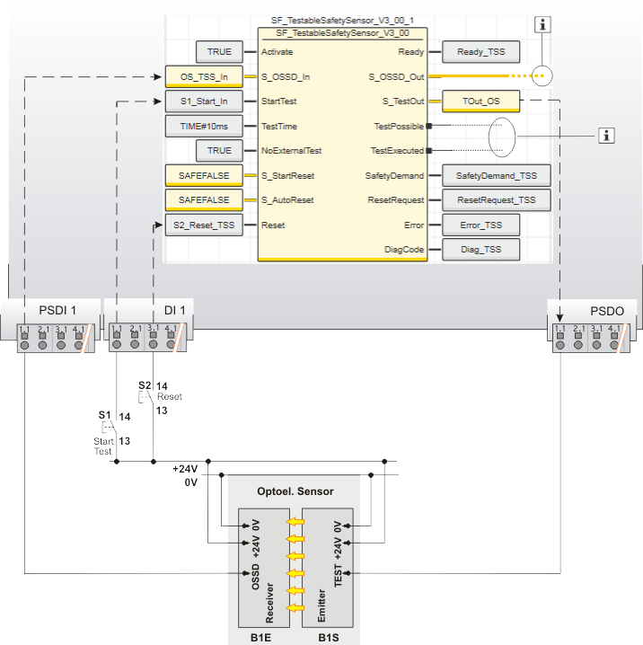
| S1 | Start test |
| S2 | Reset |
| B1 | ESPE - optoelectronic sensor |
| B1S | Emitter |
| B1E | Receiver |
 | See note above the illustration. |
Function block instantiation
The IEC 61131-3 standard defines function block instantiation. Instantiation means, a function block is defined once and can be used (instantiated) several times. This applies to all standard and safety-related FBs (local POUs as well as firmware and user library FBs).
Why instantiation?
A function block has an internal memory where it stores its own processing data (local variables). As a consequence, the output values calculated by the FB depend on the internally stored values. The same input values applied to an FB instance do not necessarily deliver the same results in another FB instance.
Therefore, it is necessary to store the internal data of the FB to a separated memory area each time the function block is processed, i.e., for each FB instance. To uniquely identify each FB instance and to clearly separate its memory area, instance names are used. The instance name of a function block has to be declared in the 'Variables' table of the POU where the FB is going to be used.
The following applies:
- Function blocks can be instantiated in other function blocks or in program POUs. Calling FBs in function POUs is not possible.
- Functions are called without instantiation because they do not have an internal memory.
Safety-related and standard (non-safety-related) code is strictly distinguished in PLCnext Engineer. If a Safety PLC is included in your project, the following applies:
- Safety-related FBs can only be instantiated in safety-related POUs but not in standard (non-safety-related) POUs.
- User-defined standard FBs can only be instantiated in standard POUs. They cannot be called in safety-related POUs.
- Particular standard firmware FBs can be instantiated in both safety-related and standard POUs.
Hinweis
When inserting a standard FB into a safety-related SNOLD network, the rules for implicit type conversion (safety-related to standard) apply. |
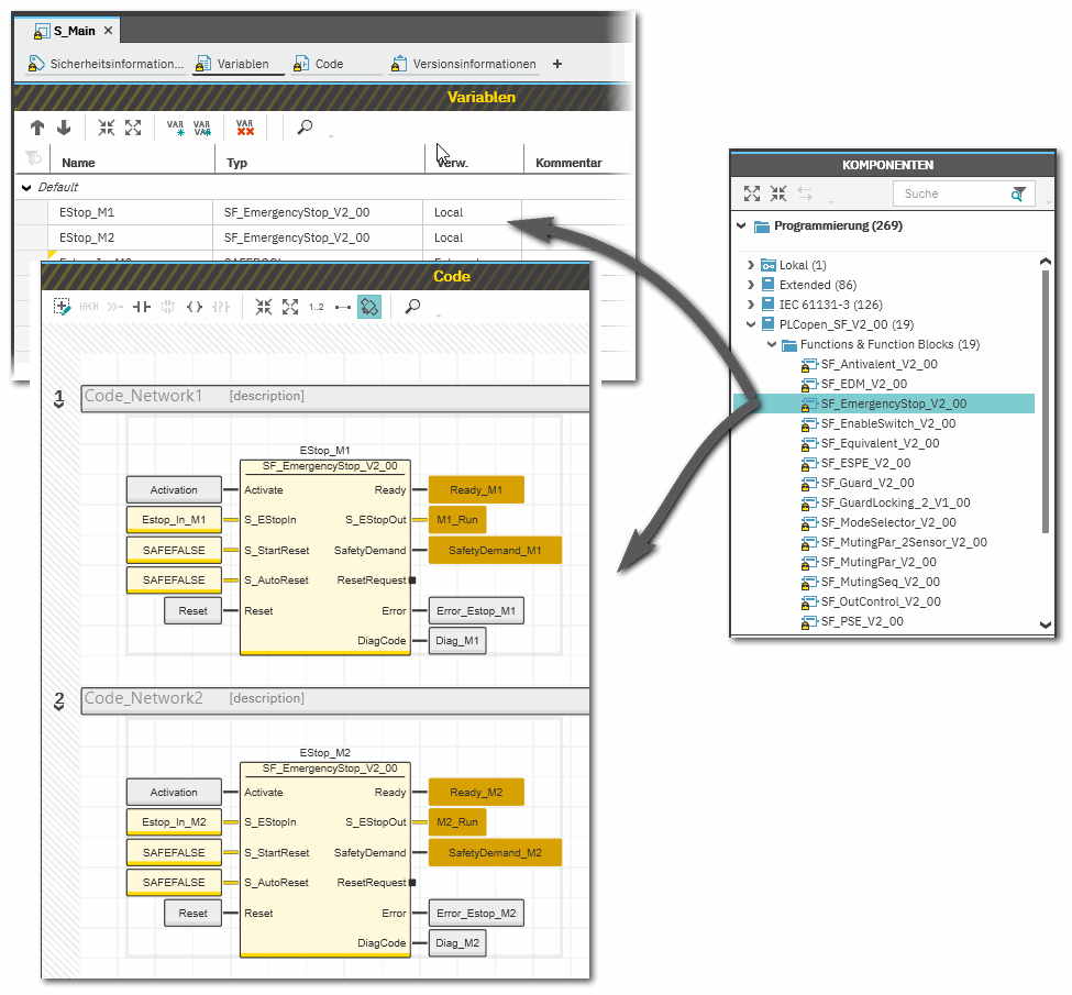
Example for the instantiation of a safety-related PLCopen function block
The safety-related PLCopen function block 'SF_EmergencyStop_V2_00' was inserted into the project via a library. It is then available in the 'Programming' category of the COMPONENTS area. There is a folder with the same name as the library that provides the FBs for insertion into the safety-related code.
The FB is to be called twice in the code of the safety-related program 'S_Main' to evaluate the status of two safety-related emergency stop command devices. For each FB instance, an instance name is declared in the 'Variables' table of the calling program: EStop_M1 and EStop_M2. The FB instances have been inserted into the code worksheet, each instance with different variables connected to its input and output formal parameters.
Additional information is available in the following sections:
|