Functional description
Dieses Thema enthält die folgenden Abschnitte:
The safety-related SF_TestableSafetySensor function block evaluates the status of connected optoelectronic safety equipment (e.g., light curtain).
The function block additionally has a test function for verifying the connected safety equipment.
| Hinweis
The safety equipment is referred to as a safety-related sensor in this documentation. |
| Hinweis
The safety-related sensor connected to the function block must meet the requirements of type 2 ESPE (Electro-Sensitive Protective Equipment) as stipulated by IEC 61496-1. This concerns the ability of a safety-related sensor to support a test function. |
| Hinweis
Since the safety equipment to be connected belongs to type 2, Cat. 2 is the highest category that can be achieved. |
The function block executes stop category 0 at its interface.
The safety-related SF_TestableSafetySensor function block evaluates the following signals for the purpose of monitoring a safety-related sensor (ESPE type 2) and for requesting a sensor test:
- Status of the safety-related sensor (normal operation/test or request for the safety-related function active)
- Request signal for the sensor test
The status of the safety-related sensor is displayed at the enable output of the function block.
Sensor test
If the optoelectronic safety equipment connected to the function block does not behave in accordance with the defined test algorithm during the test process, the function block switches its enable output to the defined safe state (S_OSSD_Out = SAFEFALSE).
If the connected safety-related sensor behaves in accordance with the test specifications during the test process, the signal at the enable output remains SAFETRUE during the test.
The function block detects the following during the test function:
- Loss of the sensitive properties of the sensor
- Exceedance of the permissible response time set at TestTime
- An irregular static SAFETRUE signal from the sensor (sensor status signal) at the S_OSSD_In input
Sensor test phases
Sensor test phases are described using the following signal sequence diagram.
| Hinweis
The diagram only shows the inputs and outputs relevant for the description, and only a successful test is displayed. |
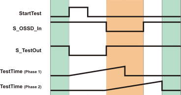
Sensor test phase 1: A rising edge at the StartTest input causes the S_TestOut output to switch to SAFEFALSE and the monitoring time set at TestTime (phase 1) to begin. The sensor must switch the S_OSSD_In input to SAFEFALSE within the period specified at TestTime.
Sensor test phase 2: Once there is a SAFEFALSE at the S_OSSD_In input, the S_TestOut output is switched to SAFETRUE and a second monitoring time measurement (phase 2) begins with the time set at TestTime. The sensor must switch the S_OSSD_In to SAFETRUE within this period.
Properties and requests at an ESPE type 2 safety-related sensor
Type 2 electro-sensitive protective equipment (ESPE) offers the possibility of carrying out periodic tests for potentially dangerous errors (for example, loss of sensory capabilities, exceedance of the set response time). The test signal simulates the activation of the safety-related sensor. When executing the test algorithm the sensor is deactivated for a maximum of 150 ms. The test is to verify that each beam of the sensor is operating according to the specification.
There is a possibility of losing the safety-related function in the event of an error between test intervals.
According to the IEC 61496-1 standard, an error must be detected either immediately by means of the next periodic test or when the sensor part is activated, and cause at least one ESPE output to be disabled.
The safety-related sensor must satisfy the safety requirements outlined in parts 1, 2, and 3 of the IEC 61496 standards and meet the criteria for the categories according to the EN ISO 13849-1 standard.
| Hinweis
Using separate/external functions, ensure that the test is carried out at regular intervals. |