Safety Function Response Time (SFRT)
What is the Safety Function Response Time (SFRT)
When planning a safety application, you must determine the correct mechanical positions of the safety equipment involved at the machine, i.e., the safety-related command devices, sensors, and actuators. This position and the physical distance of each safety equipment must fulfill the requirements of your application according to applicable standards and regulations.
To be able to perform safety distance calculations, you must know the safety function response time (SFRT).
- the receipt of the safety request signal (coming from the safety-related command device or sensor, such as an emergency stop button or a light barrier) in the safety-related input module, and
- the output of the request signal for the defined safe state of the machine at the safety-related output module. Whether the defined safe state means the standstill of the machine, or for example, a torque-free axis or a limited speed, depends on your application and must be determined in the context of your mandatory risk analysis.
| Note
The maximum permissible safety function response time (SFRTmax) depends on the relevant safety function to be implemented. |
| Note
In the application, the SFRTmax must be determined for each implemented safety function. |
The longer the SFRT of the safety system is, the greater must be the minimum distance of the safety command device/sensor from the zone of operation.
SFRT determination
The SFRT of your safety application is composed as follows:
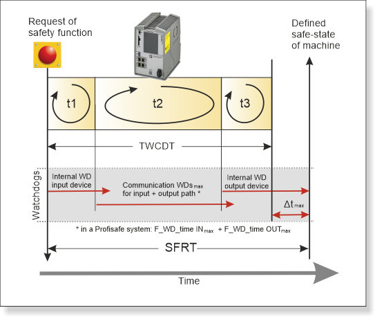
TWCDT is the Total Worst Case Delay Time which is the sum of all processing and transmission times in the respective signal path of the safety system. TWCDT is composed as follows:
TWCDT = t1 + t2 + t3
The partial delay times t1, t2, and t3 are composed as follows:
t1 = worst case input delay time
= signal processing time in the sensor and in the input safety module
Refer to the technical data sheet/user manual of the devices involved.
t2 = transmission delay + processing time
= the transfer time from input module to Safety PLC via bus coupler/Axioline
+ execution processing time in the Safety PLC (see note below)
+ transfer time from Safety PLC to output module via bus coupler/Axioline
t3 = worst case output delay time
= signal processing time in the safety-related output module
Refer to the technical data sheet/user manual of the devices involved.
| Note
The execution processing time included in t2 is displayed as 'Program Execution Time' in the Safety Cockpit. See topic "Safety PLC Diagnostics out of the Safety Cockpit" for details. |
SFRT = TWCDT + Δtmax of the longest output device WD time
For information on
Δtmax refer to the next section "Relevant Watchdogs".
| Note
The SFRT must be determined for each safety function to be implemented. |
SFRTmax = maximum Safety Function Response Time of all SFRTs in your application.
| Note
SFRT must be ≤ SFRTmax. |
|
WARNING
|
Unintended machine operation
|
Relevant Watchdogs
In a PLCnext Technology safety system, various watchdogs (WD) are implemented with which the correct function of the safety-related communication and devices can be monitored. Some watchdogs are device-internal and therefore not parameterizable, some must be parameterized in PLCnext Engineer (for example, Profisafe communication watchdog times).
Depending on the SFRTmax, you must determine the resulting maximum monitoring/watchdog times as an upper limit for each individual safety function. If, for example, the WD of a safety-related output device is set higher than the device actually needs for processing the output signal, a time delta Δt results which must be considered when planning the safety system.
The following watchdogs are relevant:- Input/output device WD: Internal watchdog time of each input/output F-Device involved in the safety
function.
Note
Refer to the PLCnext Info Center and the respective user manual for information on watchdog times within the internal F-Device function. - Communication WDs, for example, F_WD_Time INmax and F_WD_Time OUTmax in case of a Profisafe application.Each Profisafe device (F-Device) implements a watchdog for monitoring the safety-related communication. For each safety function, you must consider the sum of the maximum watchdog times set for the input devices and for the output devices involved (F_WD_Time INmax + F_WD_Time OUTmax).The sum of these watchdog times specifies the maximum internal processing time that is required for
point-to-point Profisafe communication between the input device and the
output device via the Safety PLC, even in the event of an
error, such as a telegram delay.
Further Info
Information how to determine the watchdog times can be found in the Safety PLC user manual. For the RFC 4072S controller, read chapter 2.3 "Calculating/determining the response time (Safety Function Response Time, SFRT)" of the user manual "Installation and operation in the RFC 4072S Remote Field Controller with integrated safety-related PROFINET controller (part. no. 108580_en_01).Further Info
The steps how to set the F_WD_Time value and how to evaluate the related diagnostic system variables, are described in the topic "Monitoring the Profisafe Communication".