VRRP
The 'VRRP' view shows the VRRP (Virtual Router Redundancy Protocol) topology. With VRRP, two or more physical routers are combined to create a virtual router. The virtual router has an IP and MAC address which are used for communication. If one of the physical routers fails, the virtual addresses of another router are used. For this, one of the routers in the group is defined as the master. The VRRP master owns the virtual IP address and MAC address and acts as default gateway for the network devices. All other devices are used as backup devices. If the VRRP master fails, one of the backup devices becomes the VRRP master based on the priority configured for the devices.
Physical devices with activated VRRP and virtual routers are represented in the physical topology by specific symbols (see below). Each virtual router is connected to the real routers (physical devices). If you select a virtual router in the topology, the physical router which acts as the master is shown by a specific symbol. The device tooltip shows, among others, the VRRP operation role of the device and the IP address of the virtual router. Non-VRRP devices are greyed out in the topology.
Symbols specific to the 'VRRP' view
| Note
You can switch the display of the devices between two modes: standard and individual. In standard mode, the device symbol as listed in the following table are used for the representation of the devices. In individual mode, the device icon stored in the device description file of the device (e.g., FDCML, GSDML, etc.) is shown as device symbol. To switch the display, click the  button in the toolbar of the 'Physical Topology' editor (see also the topic "Enabling/Disabling Display of Device Graphics" for further details). button in the toolbar of the 'Physical Topology' editor (see also the topic "Enabling/Disabling Display of Device Graphics" for further details). |
| Symbol | Device |
|---|---|
 | Virtual router |
 | Physical router |
 | Physical router which acts as master for a virtual router selected in the topology (see also the following example). |
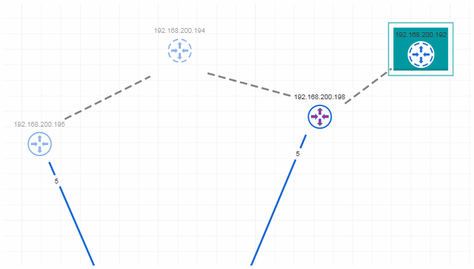
Example of a VRRP topology
In the following example, the virtual router with the IP address 192.168.200.192 is selected. The router with the IP address 192.168.200.198 acts as master for the virtual router.